
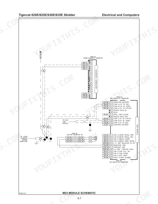
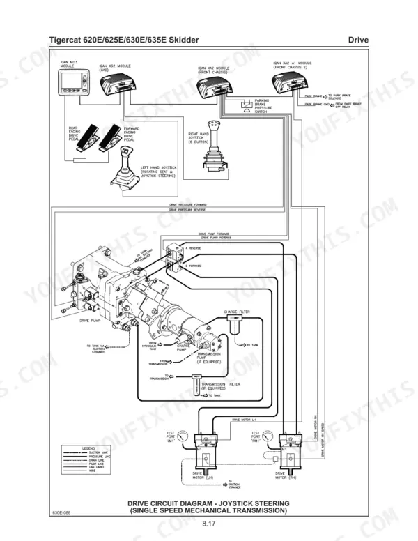
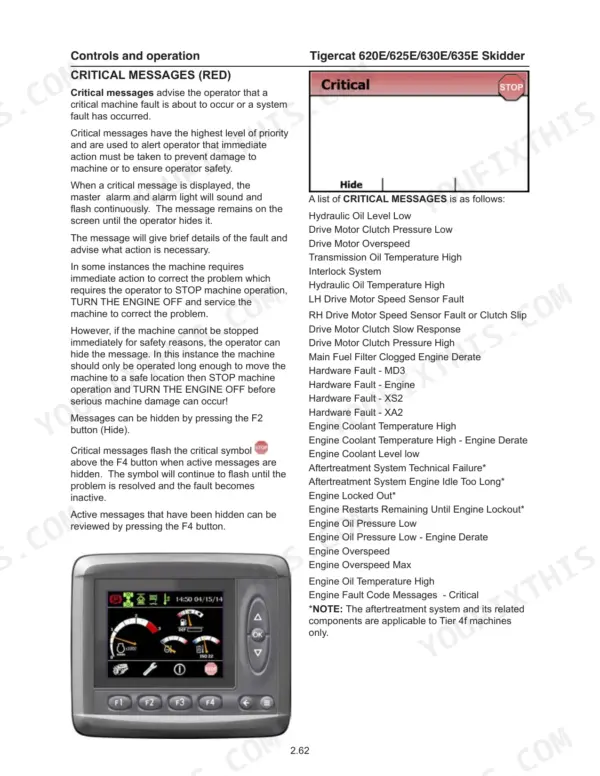
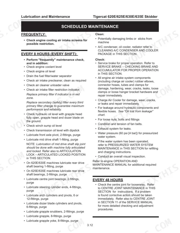
Within the hour you could have gauges on the drive pump test ports, working from this 658-page Tigercat 620E service manual PDF (OEM ID 42837AENG), which covers all four E-series skidders from the 620E through the 635E. Hydraulic schematics trace the drive, steering, grapple, arch, winch and dozer circuits, and wiring diagrams lay out the computer control modules and engine start circuit so you can chase a dead signal connector by connector. Drive is the biggest chapter in the book, running from hydrostatic setup through pump pressure checks, and fault code listings plus scheduled maintenance tables cover the diagnostic side. Set high pressure relief at 6090 psi (420 bar) and hold charge relief between 350 and 375 psi (24 to 26 bar). Every hour parked at the landing is wood left in the bush. Your copy is bookmarked and text-searchable, and it prints cleanly, so the drive chapter can go to the bench and soak up all the oil it wants.
What's Inside This Tigercat 620E, 625E, 630E, 635E Manual
| System | Pages | Key Topics |
|---|---|---|
| Introduction | 2-5 | Operator's Manual, Service Manual, Parts Catalog, Serial Numbers, Preventive Maintenance Schedule |
| Machine Identification and Serial Numbers | 6 | Machine Serial Number Plate, Front Chassis, Rear Chassis |
| S.A.E. Standards (ROPS, FOPS, Ops) | 7 | ROPS Structure, FOPS Structure, OPS Structure |
| Non-Approved Field Product Changes | 8 | |
| Regulatory Information | 9 | Telematics Module, Iqan-G11, Radio |
| Warranty–Epa | 10-11 | Emission Control Information Label, Fuel Injection System, Air Induction System, Positive Crankcase Ventilation System, Exhaust After Treatment Devices |
| Ec Declaration 620e 625e 630e | 12-14 | Self Propelled Forestry Machine, Wheeled Grapple Skidder, Articulated Frame, Grapple System, Tree-Length Harvesting System |
| Safety | 15-52 | Articulation Lock, Battery Disconnect Switch, Battery Safety, Cab Exits, Cab Safety Cable, Cab Support Brace, Diesel Exhaust Fluid, Emergency Cab Exits |
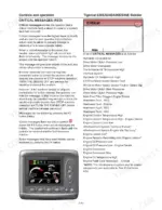
| Controls and Operation | 53-180 | Cab Controls, Computer Control System |
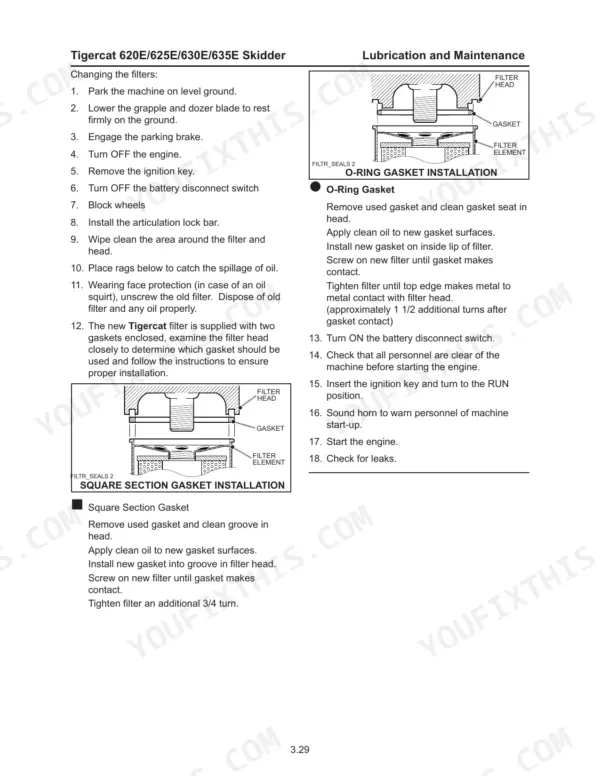
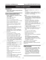
| Lubrication and Maintenance | 181-290 | Tigercat Fluid Analysis Program, Scheduled Maintenance |
| Electrical and Computers | 291-344 | Computer Control System, Computer Modules |
| Engine Start and Stop | 345-354 | Engine Start Circuit |
| Drive | 355-492 | Hydrostatic Setup Procedure, Drive Pump Pressure Checks |
| Brakes and Differential Locks | 493-514 | Accumulator, Parking Brake Caliper |
| Cooling System | 515-530 | Cooler Package, Variable Pitch Fan |
| Steering and Centre Joint | 531-554 | Steering Control Valve, Centre Joint |
| Grapple, Arch and Boom | 555-600 | Control Valve, Grapple Rotate Assembly |
| Winch | 601-644 | Allied Winch, Carco Winch |
| Dozer Blade | 645-658 | Dozer Circuit Description |
Quick Reference Specifications
| Specification | Value | Page |
|---|---|---|
| Slew bearing cap screw torque | 386 N-m (285 lbf-ft) | p. 488 |
| Hydraulic oil double element filter bypass valve pressure | 25 psi (1.7 bar) | p. 208 |
| Charge pressure filter bypass valve pressure | 50 psi (3.5 bar) | p. 210 |
| Bearing heating temperature | 250°F (121°C) | p. 475 |
| Bearing feeler gauge clearance | 0.001-0.002 in (.025-.051 mm) | p. 475 |
| B17-B20 planet gear bearing recess | 9.5 mm (0.375 in) | p. 481 |
| Axle shaft endplay | 0.090 to 0.110 in (2.29 to 2.80 mm) | p. 483 |
| Wheel end bolt torque | 300 lbf-in (407 N-m) | p. 483 |
| Input gear cover bolt torque | 75 Nm (55 ft-lbf) | p. 490 |
| Bogie axle shaft end play | 0.090-0.110 in (2.29-2.79 mm) | p. 483 |
| Engine High Idle (Tier 2) | 2100 rpm | p. 389 |
| Engine High Idle (Tier 4f) | 2200 rpm | p. 389 |
Tigercat 620E, 625E, 630E, 635E Common Problems This Manual Covers
Tigercat 620E, 625E, 630E, 635E skidder engine start circuit fault, starter lockout active and engine will not crank
Check the engine start circuit following the description on page 345 before condemning the starter. Verify the starter lockout is not holding the circuit open, then test the main pump unloading valve, since it is part of the start circuit. Trace any open condition through the wiring diagram and repair the break.
Manual Section: Engine Start and Stop p. 345Hydrostatic drive pump charge pressure low and hydraulic neutral out of adjustment, skidder creeps in neutral
Measure drive pump charge pressure before touching anything else, because it is the first step in the hydrostatic setup. Charge pressure relief should hold 350-375 psi (24-26 bar) as listed on page 359. With charge correct, adjust hydraulic neutral per the Drive Pump Pressure Checks until the machine sits still with the drive control centered.
Manual Section: Drive p. 359Drive pump high pressure relief or motor max current out of spec, skidder lacks drive pull under load
Verify high pressure relief at 6090 psi (420 bar) using the setting listed on page 359. Then measure final motor max current against page 413: 940-1010 mA on a 165cc drive pump, 870-940 mA on a 210cc pump. Confirm which pump is on the machine before adjusting, since the windows differ.
Manual Section: Drive p. 413Parking brake caliper fails the parking brake release test and will not release
Check parking brake caliper operation against the brake circuit description on page 493. Before blaming the caliper, measure main pump standby at 200-250 psi and POR at 3500-3600 psi using page 513 to rule out a supply problem. Then repeat the parking brake release test from the hydrostatic setup procedure.
Manual Section: Brakes and Differential Locks p. 493Steering priority valve or external priority relief valve set wrong, articulation steering slow and weak
Test the priority valve relief setting against 3000 psi (205 bar) per page 532. Next, check the external priority relief valve on page 534: it must sit at least 200 psi (13.8 bar) below the main pump POR setting. If the two settings crowd each other, readjust the external relief before chasing the steering control valve.
Manual Section: Steering and Centre Joint p. 532Centre joint bearing retaining bolts loose, play felt at the articulation joint
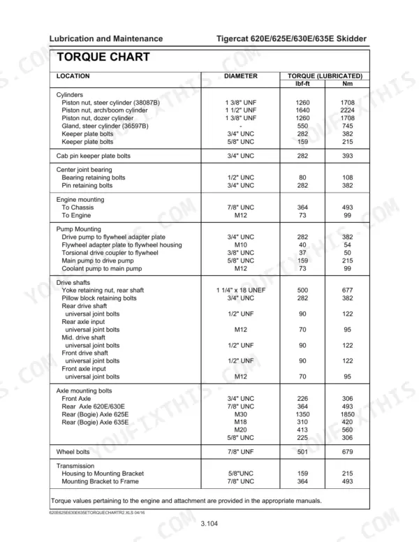
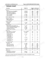
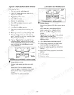
Torque the bottom centre joint retainer bolts in sequence to 282 lbf-ft (382 Nm) following pages 551-552. On the bearing retainer plate, apply blue 243 Loctite and torque the six bolts to 80 lbf-ft (108 Nm) as shown on page 552. Recheck for movement at the joint before returning the skidder to work.
Manual Section: Steering and Centre Joint p. 551Frequently Asked Questions
What are the torque specifications for the wheel bolts on the Tigercat 620E/625E/630E/635E skidder?
The wheel bolts for the Tigercat 620E/625E/630E/635E skidder must be torqued to 501 lbf-ft (679 Nm). p. 492
How do I check the drive pump charge pressure on a Tigercat 620E, 625E, 630E, 635E skidder?
Connect a 0-1000 psi (0-70 bar) gauge to the CHARGE test port. With the engine at low idle, the reading should be 300-400 psi (21-28 bar). p. 382
How often should the engine oil and filter be replaced on the Tigercat skidder?
The engine oil and filter should be replaced every 250 hours of operation. p. 193
What is the correct torque for the centre joint bearing retaining bolts on a Tigercat 620E, 625E, 630E, 635E skidder?
The centre joint bearing retaining bolts should be torqued to 80 lbf-ft (108 Nm). p. 284
What is the required end play for the planetary wheel end axle shaft?
The final axle shaft end play must be set between 0.090 to 0.110 inches (2.29 to 2.80 mm). p. 483
How will I receive this Tigercat 620E Service Manual?
This is a 658-page searchable PDF ready for immediate download. Works on any device, so pull it up on your phone while you're under the hood. No shipping, no waiting.
Does this Tigercat 620E manual allow printing?
Yes. Many buyers print one chapter at a time for their own shop and keep the rest on a tablet.

Reviews
There are no reviews yet.