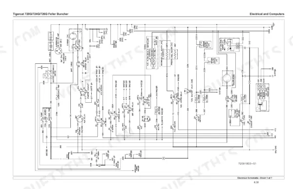
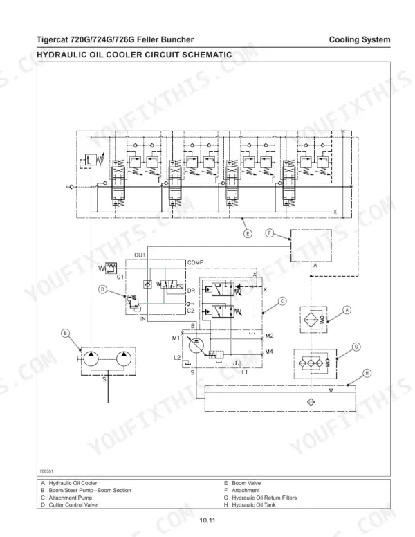
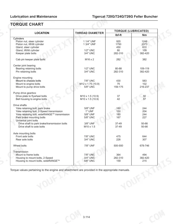
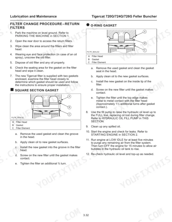
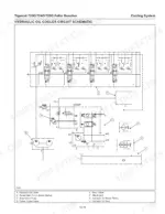
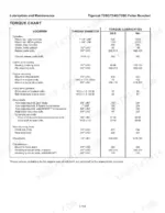
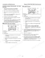
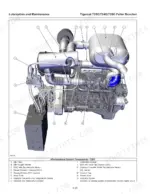
Locating the machine serial number plate and engine identification label is the first job in the 572-page Tigercat 720G service manual PDF, OEM ID 47055AENG, which covers the 720G, 724G and 726G feller bunchers. Wiring diagrams trace the electrical and computer systems and the engine start circuit, while hydraulic schematics map the boom valve, port reliefs and lift cylinder circuit. Other sections cover the pilot system, hydrostatic drive, parking brake, cooling fan, center joint, tilt, saw drive, and clamp and accumulating arms for saw and shear heads. Replace the air cleaner unloader valve every 1000 hours. Torque keeper plate bolts to 282-310 lbf-ft (382-420 Nm). When your scheduled maintenance reaches the hydraulic filters, you have the filter restriction switch activation at 1.4 bar (20 psi) and the drive pump charge filter bypass at 3.5 bar (50 psi) on hand. Bookmarked and text-searchable, the PDF stays on your laptop or tablet wherever the machine is.
What's Inside This Manual
| System | Pages | Key Topics |
|---|
| Introduction | 5 | Serial Numbers |
| Machine Identification and Serial Numbers | 6 | Machine Serial Number Plate, Machine Serial Number Stamp, Engine Identification Label, Engine Serial Number Plate |
| Standards for Machine Operator Protective Structures | 7 | ROPS, FOPS, OPS |
| Non-Approved Field Product Changes | 8 | Unauthorized Attachments |
| Regulatory Information | 9 | Telematics Module, Iqan-G11, Inmarsat Modem, Iridium Modem, Radio |
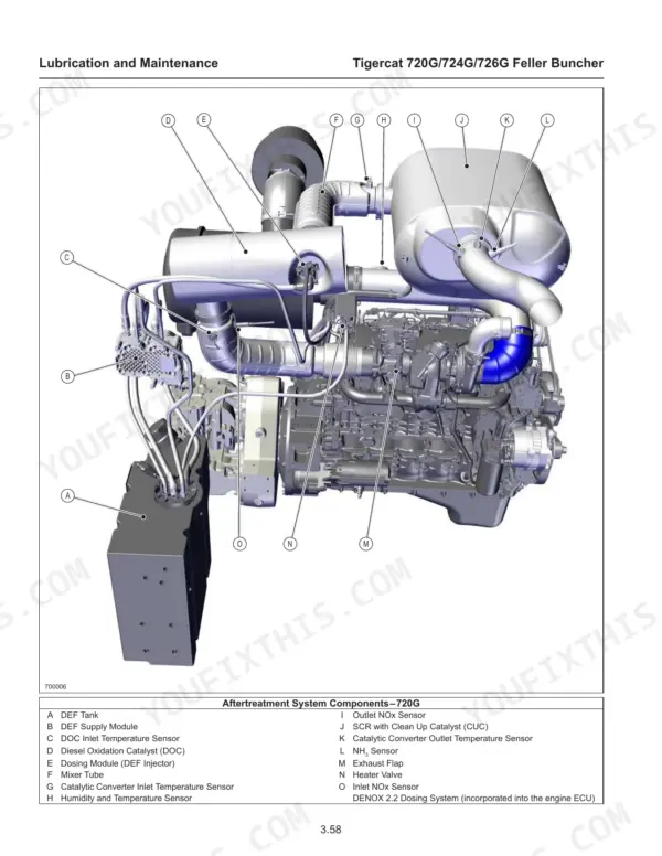
| Warranty-EPA | 10-12 | Emission Control Label, Fuel Injection System, Air Induction System, PCV System, Exhaust After Treatment Devices, EGR System |
| Safety | 13-66 | General Safety Precautions, Lightning Safety Awareness, Fire Prevention |
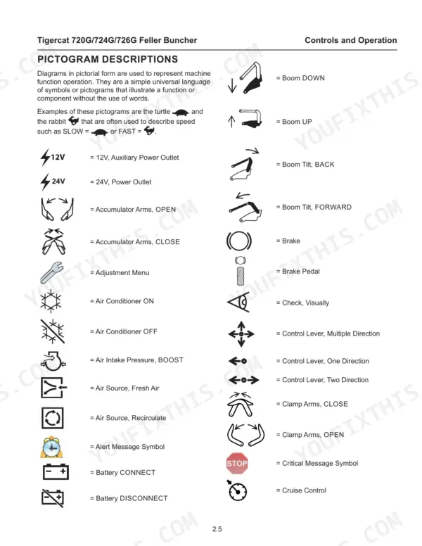
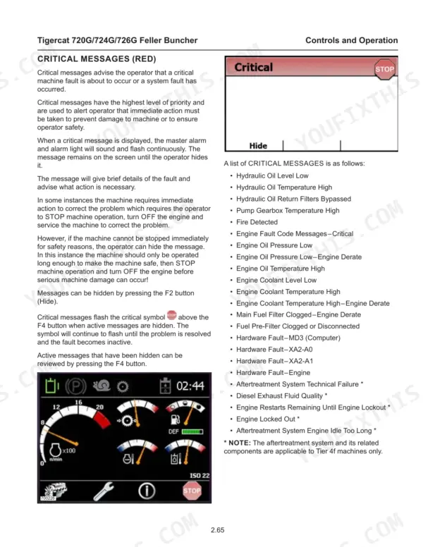
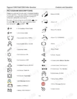
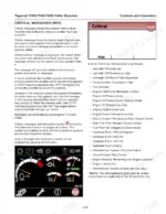
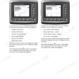
| Controls and Operation | 67-174 | Pictogram Descriptions, Computer Control System |
| Lubrication and Maintenance | 175-294 | Scheduled Maintenance |
| Hydraulic System | 295-316 | Boom Valve |
| Pilot System | 317-336 | Accumulator Charge Valve |
| Electrical and Computers | 337-378 | Machine Program Updates |
| Engine | 379-388 | Pump Drive Gearbox, Pump Drive Coupler, Start Circuit, Electrical Schematic |
| Drive | 389-452 | Hydrostatic Drive System |
| Brakes and Differential Locks | 453-464 | Parking Brake |
| Cooling System | 465-494 | Cooling Fan |
| Steering and Center Joint | 495-510 | Center Joint |
| Lift Boom | 511-522 | Boom Valve, Lift Cylinders, Joystick, Port Reliefs, Circuit Components, Circuit Schematic |
| Tilt | 523-534 | Boom Valve, Tilt Spool Section, Port Relief Valves, Tilt Cylinders, Joystick Pilot Valve |
| Saw Drive | 535-546 | Attachment Pump, Cutter Control Valve, Hydraulic Motor, Pilot-Operated Check Valve, Relief Valve Cartridge |
| Clamp and Accumulating Arms with Saw | 547-558 | Boom Valve, Clamp Arm Cylinders, Accumulating Arm Cylinders, Clamp Arm Pedal Pilot Valve, Port Relief Valves |
| Clamp and Accumulating Arms with Shear | 559-572 | Boom Valve, Clamp Arm Cylinders, Shear Arm Cylinders, Accumulating Arm Cylinders, Clamp/Shear Arm Pedal Pilot Valve, Port Relief Valves |
Quick Reference Specifications
| Specification | Value | Page |
|---|
| Return filter bypass valve pressure | 1.7 bar (25 psi) | p. 205 |
| Filter restriction pressure switch activation pressure | 1.4 bar (20 psi) | p. 205 |
| Air cleaner unloader valve replacement interval | 1000 hours | p. 193 |
| Keeper plate bolts | 282-310 lbf-ft (382-420 Nm) | p. 288 |
| Bearing retaining bolts | 80-88 lbf-ft (109-119 Nm) | p. 288 |
| Drive Pump Charge Pressure Relief Valve pressure | 29 bar (425 psi) | p. 415 |
| Drive Motor POR pressure | 279 bar (4050 psi) | p. 411 |
| Steer Right 'B' Port Relief pressure | 221 bar (3200 psi) | p. 506 |
| Steer Left 'A' Port Relief pressure | 221 bar (3200 psi) | p. 506 |
| Engine High Idle Speed | 2200 ± 25 rpm | p. 89 |
| Engine Low Idle Speed | 900 ± 25 rpm | p. 89 |
| Hydraulic Tank Capacity (720G/724G) | 160 L | p. 202 |