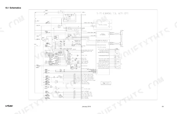
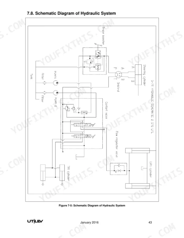
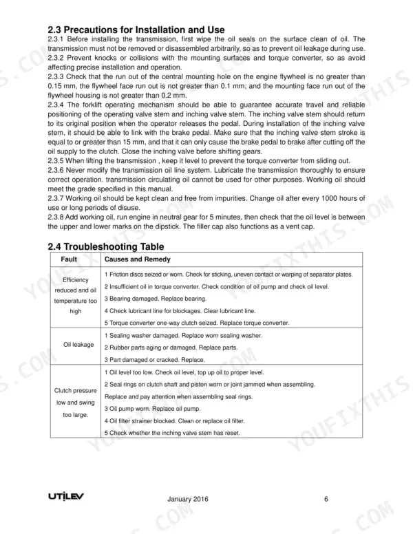
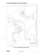
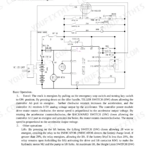
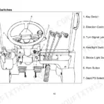
Every UT50, UT60 and UT70 internal combustion counterbalanced forklift truck, P variants included, is covered by this 80-page Utilev UT50P, UT60P, UT70P service manual PDF (OEM ID 76500014), so you know it matches your fleet before you buy. Wiring schematics trace the fuse box, combination switch and instrument cluster circuits, while the hydraulic system schematic maps oil from the pump through the multi-way directional valve and flow regulator to the lift and tilt cylinders. Troubleshooting tables cover the torque converter, drive axle, steering, brakes and mast, and the lifting section takes you through mast removal, adjustment and commissioning, plus Cummins and GM 4.3L engine diagnostics. On 5T to 7T trucks, set the main safety valve at 19±0.25 MPa and the steering safety valve at 9.8±0.25 MPa. One wrong relief setting can cost you a pump. The bookmarked, text-searchable PDF travels on a laptop or phone to wherever the truck sits, dock or yard.
What's Inside This Manual
| System | Pages | Key Topics |
|---|
| Powertrain | 5-7 | Power Configuration, Engine Parameters, Emission Values, Fault Diagnosis Connector |
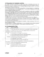
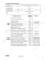
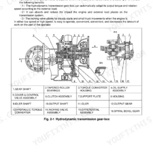
| Hydrodynamic Transmission, Torque Converter | 8-11 | Overview, Main Technical Parameters, Troubleshooting Table, Drive Shaft |
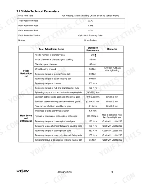
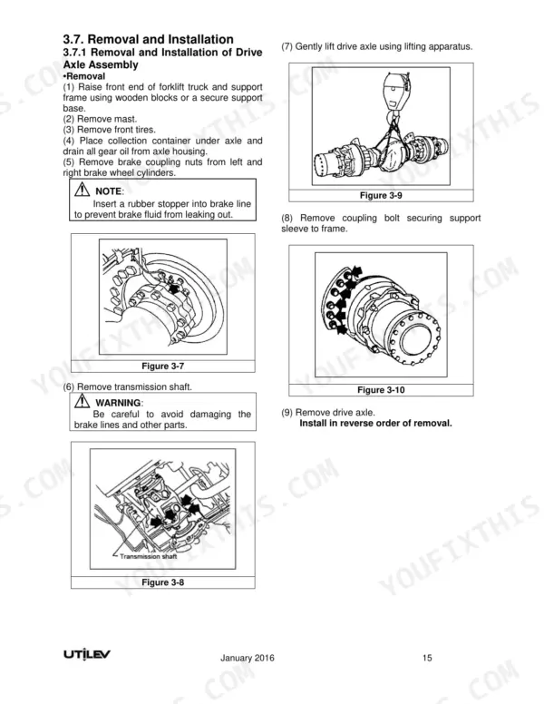
| Drive Axle Assembly | 12-25 | Basic Structure and Working Principle of Drive Axle, Periodic Technical Services, Drive Axle Oil Adding/Draining Procedures and Oil Quantity, Lifting the Drive Axle |
| Steering Axle | 26-29 | General Specifications, Structural Diagram of Steering Axle |
| Steering System | 30-32 | Steering System Troubleshooting, Overview |
| Braking System | 33-42 | Specifications, Troubleshooting, Service Brake Pedal Height and Free Travel, Brake Master Cylinder, Hydraulic Booster, Brakes and Brake Wheel Cylinder, Parking Brake |
| Hydraulic System | 43-47 | Specifications, Troubleshooting, Oil Pump, Multi-Way Directional Valve, Flow Regulator Valve, Lift Cylinder, Tilt Cylinder, Schematic Diagram of Hydraulic System |
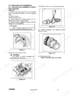
| Lifting System | 48-58 | Assembly and Commissioning Data, Fault Diagnosis and Troubleshooting, Overview, Mast Removal, Installation and Adjustment, Removal and Installation of Lift Cylinders |
| Engine Diagnostics | 59-61 | Cummins Engine Diagnostics, GM Engine Diagnostics |
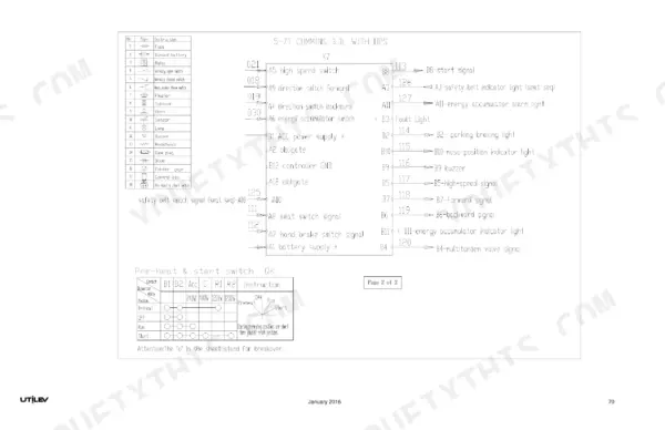
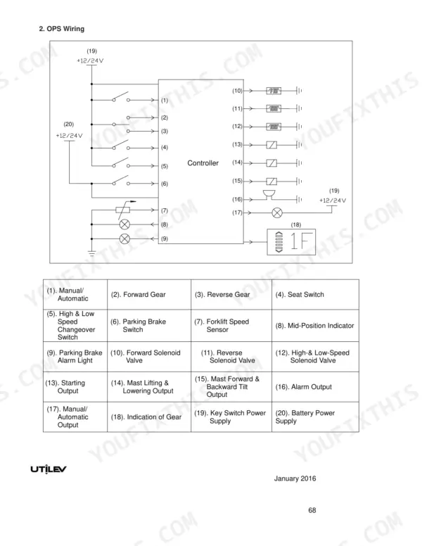
| Electrical System | 62-80 | Inspection, Fuse Box Assembly, Combination Switch, Instrument Cluster Assembly |
Quick Reference Specifications
| Specification | Value | Page |
|---|
| All Models |
| Charging Pump Displacement | 21 ml/r | p. 8 |
| Rated Power | 74 kW | p. 5 |
| Transmission Oil Capacity | 25 L | p. 8 |
| Main Reduction Unit Oil Capacity | 10 L | p. 16 |
| Final Reduction Unit Oil Capacity | 1.5 L | p. 16 |
| Steering Tire Pressure | 0.83 MPa | p. 26 |
| 5T-7T |
| Main Safety Valve Pressure | 19±0.25 MPa | p. 43 |
| Mono-stable diverter valve flow | 18-22 L/min | p. 43 |
| Lift chain dimension C | 25–30 mm | p. 48 |
| 5T-6T |
| Inner/outer side rollers to mast flange clearance | 0.2~1 mm | p. 48 |
| UT50/60/70P (Diesel) |
| Rated Speed | 2200 rpm | p. 5 |
| UT60/70P (Dual Fuel) |
| Rated Speed | 2300 rpm | p. 5 |