
The Utilev UT 1.5 WE service manual PDF strips the electric pallet truck down cover by cover across 29 pages (OEM ID 76502807), from the upper and rear panels through the brake, drive motor, wheels, battery and handle. An electrical schematic traces the travel, lift, lower and alarm circuits through the key switch, tiller microswitch, electromagnetic brake and BDI display, and troubleshooting charts follow a truck that cannot travel, lift or lower back to the failed part. Every menu on the controller handheld unit is mapped, from Parameters and Monitor to Present Errors and Fault History, along with the system pressure adjustment and hydraulic oil fill. Meter the brake coil at 31 ± 5 Ω, and expect the 650 W drive motor to pull a rated 38 A. A pressure setting pulled from memory can blow a seal under load. Bookmarked and text-searchable, the PDF takes you from diagnosis to your truck moving pallets again.
What's Inside This Utilev UT 1.5 WE Manual
| System | Pages | Key Topics |
|---|---|---|
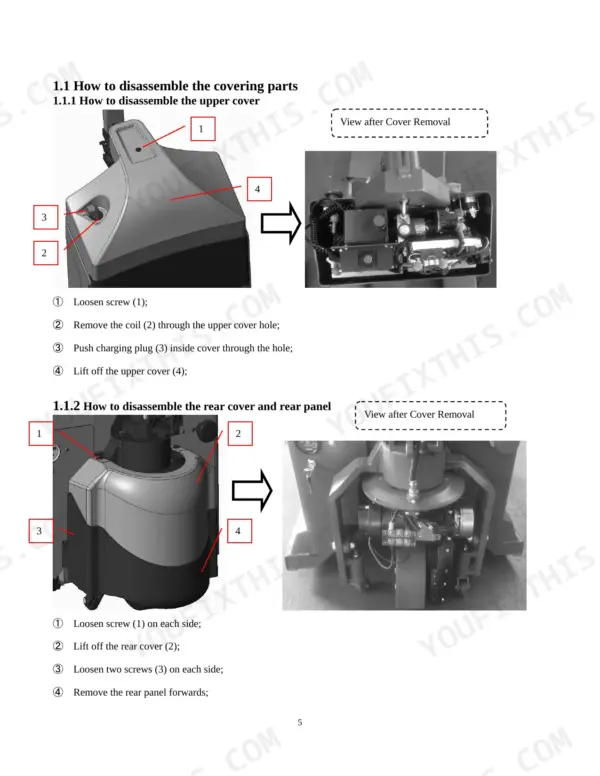
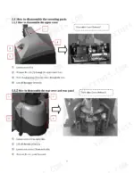
| Overview | 3-6 | How to Disassemble the Covering Parts (How Disassemble: Upper Cover, Rear Cover and Rear Panel, Case Cover), Internal Overview |
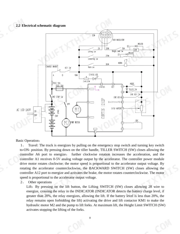
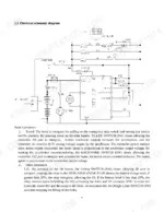
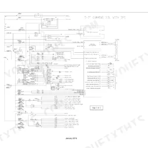
| Electrical Layout and Schematic Diagram | 7-8 | Tiller Handle, Microswitch, Drive Motor, Electromagnetic Brake, BDI Display, Key Switch, Travel, Lift, Lower and Alarm Operation |
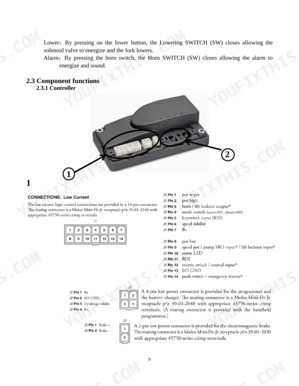
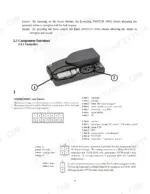
| Component Functions | 9-13 | Controller, Operation Panel, Operation Handle |
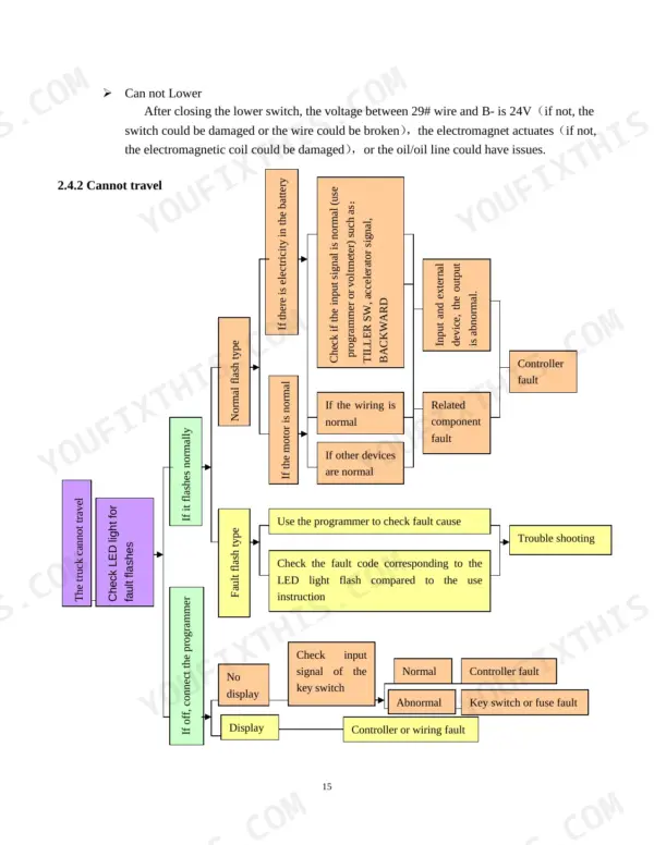
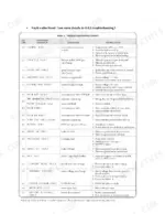
| Trouble Shooting | 14-17 | Drive Motor, CAN Not Lift or Lower, Cannot Travel |
| Controller Handheld Unit | 18-21 | System Info Menu, Parameters Menu, Monitor Menu, Diagnostics Menu, Present Errors Folder, Fault History Folder |
| Maintenance of Mechanical Structure | 22-29 | How to Disassemble the Brake, How to Disassemble the Motor, How to Disassemble the Wheel, How to Disassemble the Battery, How to Disassemble the Handle |
Quick Reference Specifications
| Specification | Value | Page |
|---|---|---|
| Electromagnetic brake coil resistance | 31 ± 5 Ω | p. 16 |
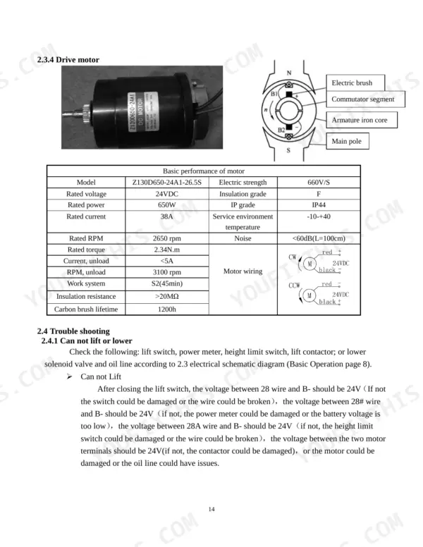
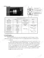
| Drive motor rated power | 650 W | p. 14 |
| Drive motor rated current | 38 A | p. 14 |
| Rated power | 650W | p. 14 |
| Rated current | 38A | p. 14 |
| Rated RPM | 2650 rpm | p. 14 |
| Carbon brush lifetime | 1200h | p. 14 |
| Brake resistance (C1/C2) | 31±5Ω | p. 16 |
| Motor resistance (M1/M2) | 0±0.5Ω | p. 17 |
| Fuse (10A) | 10A | p. 7 |
| Fuse (50A) | 50A | p. 7 |
| Max. system pressure | 115% of rated capacity | p. 27 |
Utilev UT 1.5 WE Common Problems This Manual Covers
Utilev UT 1.5 WE pallet truck lift circuit check, lift switch pressed but forks will not lift
Close the lift switch and measure 24V between the 28 wire and B- following page 14. No voltage means a damaged switch or a broken wire. Check the power meter and battery voltage, then look for 24V at the 28A wire to clear the height limit switch. No 24V across the motor terminals points to the contactor. Otherwise suspect the motor or the oil line.
Manual Section: Trouble Shooting p. 14Lower switch closed but forks will not come down and the lowering electromagnet does not actuate
Close the lower switch and measure 24V between the 29# wire and B- as shown on page 15. No voltage means a damaged switch or a broken wire. With voltage present, confirm the electromagnet actuates. If it does not, the electromagnetic coil is damaged. If it actuates, check the oil and oil line, and check the level with the dip stick on page 28. Do not fill past the Max. fluid level marked on the gauge.
Manual Section: Trouble Shooting p. 15Truck will not travel and the status LED shows fault flashes or stays off
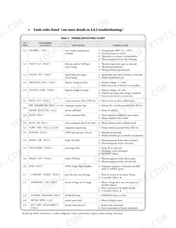
Check the LED for fault flashes and match the flash type against the fault codes on page 16. Plug the 1313 handheld programmer into the charger/programmer port and read the Present Errors folder (page 21). Cycle the control system off and on to see whether a temporary fault clears. If the programmer shows no display, check the key switch input signal and the 10A and 50A fuses shown on page 7.
Manual Section: Trouble Shooting p. 15Electromagnetic brake coil suspect on the drive unit, controller reporting a brake on/off fault code
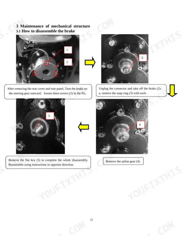
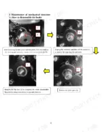
Measure brake coil resistance across C1 and C2 and compare it to 31±5Ω, per page 16. If the reading is out of range, remove the rear cover and rear panel, turn the brake outward and loosen the three screws. Unplug the connector, then remove the brake, snap ring, spline gear and flat key following page 22. Reassemble in the opposite order.
Manual Section: Fault codes p. 16Drive motor suspect after a motor open or motor stalled fault flashes on the LED
Measure resistance across M1 and M2 and compare it to 0±0.5Ω following page 17. An open reading confirms a motor or wiring fault. Compare brush hours against the 1200h carbon brush lifetime listed on page 14. To pull the motor, remove the brake first, disconnect the motor wiring, loosen the four lock screws and swing the motor out slowly per page 23.
Manual Section: Trouble Shooting p. 17Controller fault suspected when inputs read normal but outputs to the drive motor stay abnormal
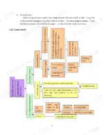
Discharge the B+ and B- terminals with a 30Ω, 5W resistor before testing, per page 10. In resistance mode, check for B+ to B- above 40KΩ, B+ to M1 and B+ to M2 above 80KΩ, and M1 to M2 above 60KΩ. In polarity mode, B- to M1 and B- to M2 should read 0.3 to 0.6 V. Readings outside these ranges point to the controller.
Manual Section: Controller MOSFET checks p. 10Frequently Asked Questions
How do I clear the thermal fault code 1,1?
To clear a thermal fault, check the controller temperature and allow the unit to cool if it is out of range. If the temperature is normal but the fault persists, the controller temperature sensor may be damaged, requiring a replacement of the controller. p. 16
How do I troubleshoot throttle fault code 1,2?
Throttle fault 1,2 indicates the throttle input wire is open or shorted, the throttle potentiometer is defective, or the wrong throttle type is selected. Refer to the test methods on page 17 for detailed diagnostic procedures. p. 16
What does hardware fail-safe fault code 4,2 mean?
Fault code 4,2 indicates the motor voltage is out of range and does not correspond to the throttle request, which may be caused by a short in the motor or wiring, or a controller failure. First, check for short circuits or bonding in the motor wires; if the wiring is normal, the motor must be replaced. p. 17
How do I test the electromagnetic brake?
Set your multimeter to resistance measurement (Ω) and measure the resistance between C1 and C2. The normal value should be approximately 31±5Ω; a higher reading indicates an open circuit in the brake or wiring, while a lower reading indicates a short circuit. p. 16
What is the procedure for adjusting the system pressure on the Utilev UT 1.5 WE?
After removing the upper cover, locate the relief valve cover on the hydraulic power unit. Adjust the screw using a hexagon spanner wrench; turn clockwise to increase pressure, noting that the maximum pressure is 115% of the rated capacity. p. 27
How will I receive this Utilev UT 1.5 WE Service Manual?
Straight to your device: 29 pages of searchable Service Manual, downloadable the moment payment goes through.
Can I print just the pages I need from this Utilev UT 1.5 WE manual?
Yes. Print individual pages or full chapters for your own shop use, on letter or A4 paper.


Reviews
There are no reviews yet.