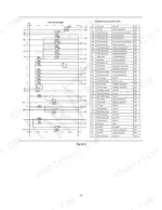
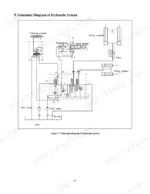
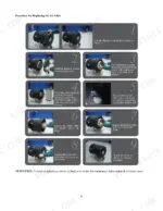
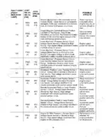
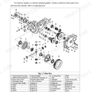
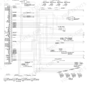
When a figure on the Utilev UT80-100P internal combustion counterbalanced forklift truck is in doubt, this 98-page factory book (OEM ID 76501365) settles it for the UT80-100P DSL trucks. Hydraulic schematics in this Utilev UT80-100P service manual PDF trace oil from the pump through the control valve and flow regulator to the lift and tilt cylinders, while the circuit diagram maps the key switch, instrument cluster and control module wiring. Troubleshooting charts cover the hydraulic transmission, drive axle, brakes and mast, with procedures for mast removal and adjustment, spiral bevel gear meshing and bleeding the brake lines. Change engine oil and filter every 250 hours or 3 months, and hold transmission main oil pressure at 1.2 to 1.5 MPa. A made-up pressure figure burns clutch packs. Your bookmarked, text-searchable PDF keeps the factory number in front of you until the truck is back on shift, lifting loads.
What's Inside This Manual
| System | Pages | Key Topics |
|---|
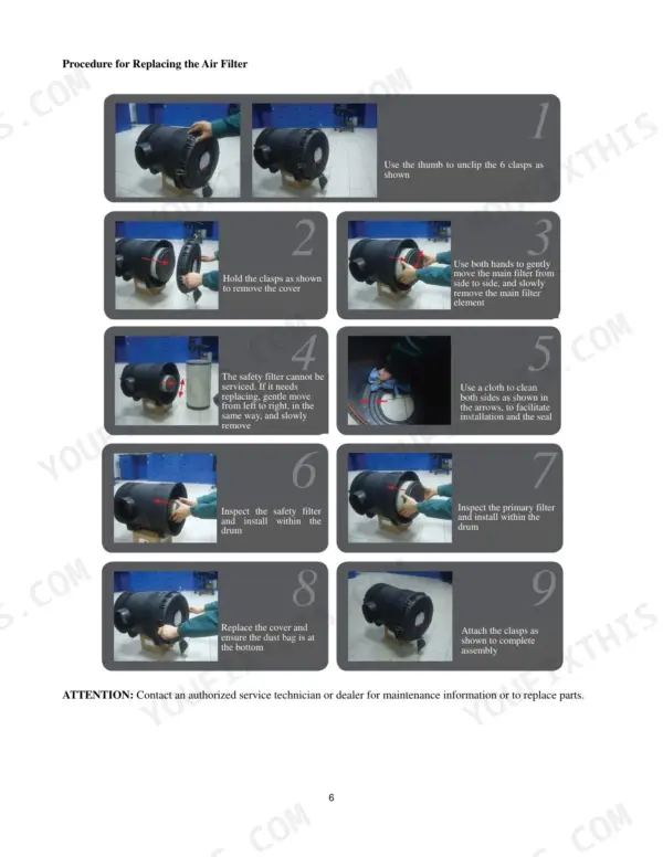
| Power System | 5-11 | Engine, Intake System, Exhaust System, Cooling System |
| Universal Joint | 12 | Flange Yokes, Cross Shaft, Bearing, Centring Yoke, Needle Bearings |
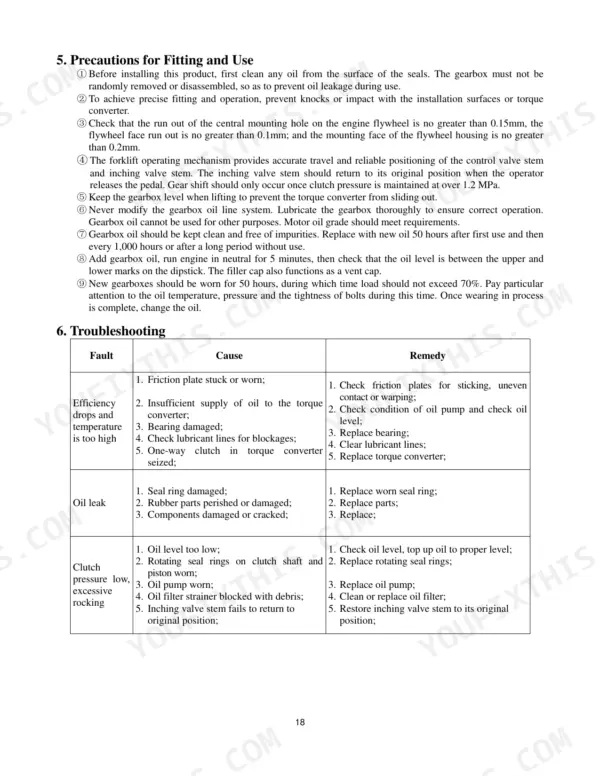
| Hydraulic Transmission Gearbox | 13-22 | Overview, Main Technical Parameters, Principles of Operation, Structural Overview, Troubleshooting |
| Drive Axle Assembly | 23-34 | Drive Shaft Basic Structure and Working Principles, Periodic Technical Services, Lubricating the Drive Shaft, Lifting the Drive Axle |
| Steering System | 35-39 | Hydraulic Steering Mechanism, Steering Axle |
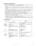
| Brake System | 40-51 | Specifications, Troubleshooting, Pedal Height and Free Travel, Master Cylinder and Accumulator, Parking Brake, Service Brake, Troubleshooting Hydraulic Brake Issues |
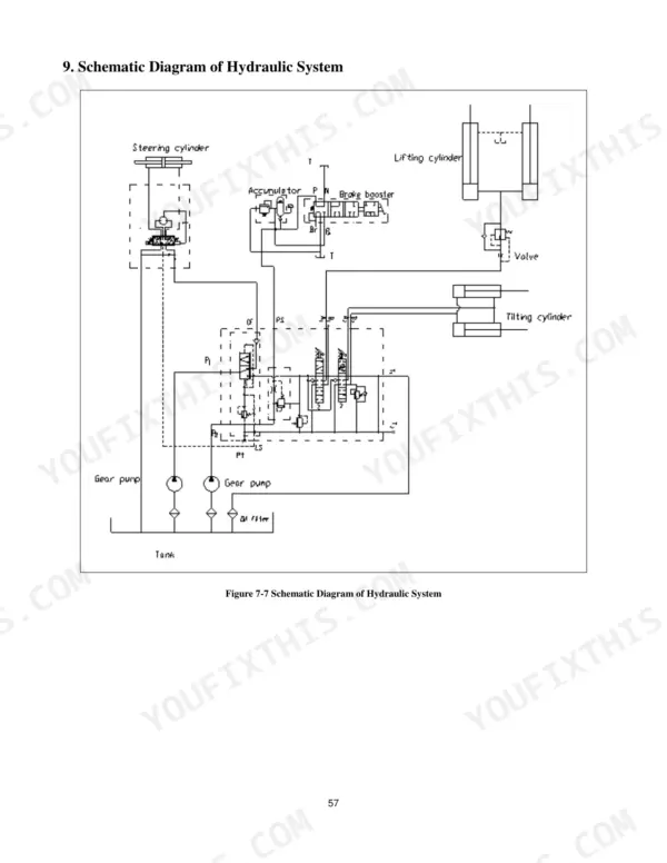
| Hydraulic System | 52-61 | Oil Pump, Control Valve, Rotating Pipe Filter, Flow Regulator Valve, Lift Cylinder, Tilt Cylinder, Bleeding Air From the Hydraulic System |
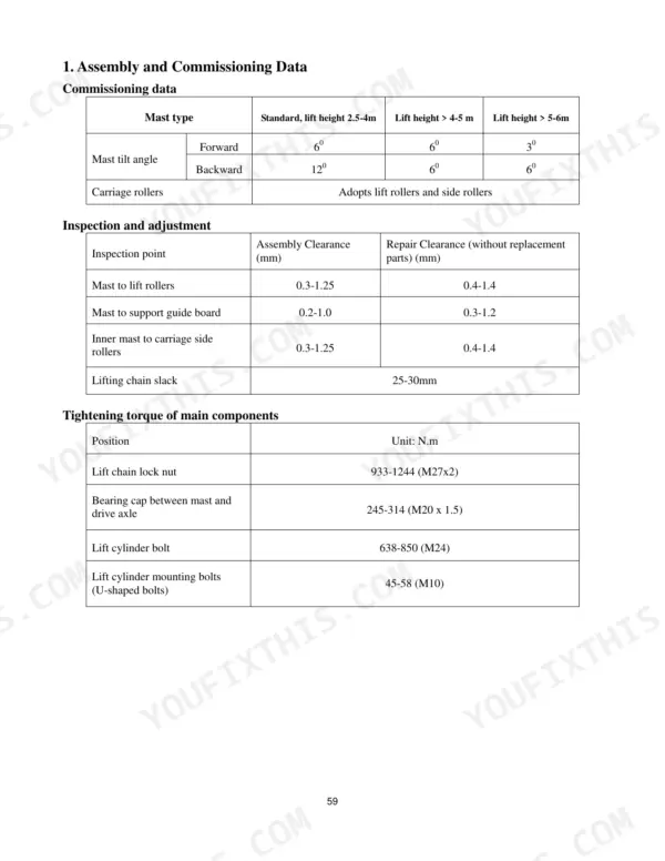
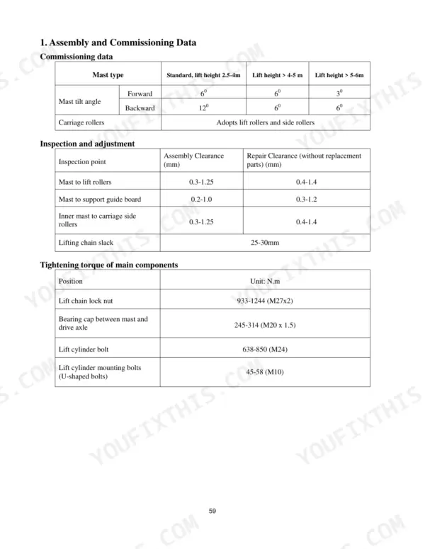
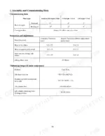
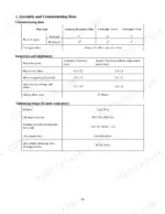
| Lifting System | 62-69 | Assembly and Commissioning Data, Fault Diagnosis and Troubleshooting, Overview, Mast Removal, Fitting and Adjustment, Removal and Fitting of Lift Cylinders |
| Removal and Fitting of the Overhead Guard | 70-71 | Right Trim, Left Trim, Handle, Cover Plate, Air Vent, Cross Brace Assembly |
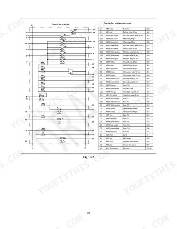
| Electrical System | 72-98 | Control Module |
Quick Reference Specifications
| Specification | Value | Page |
|---|
| Engine oil capacity | 8-12 L | p. 6 |
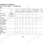
| Lubricant and oil filter replacement cycle | 250 hours, 3 months, or 10,000 kilometres | p. 7 |
| Fuel filter replacement cycle | 250 hours or 10,000 kms | p. 7 |
| Air filter cleaning pressure | 500 kPA | p. 9 |
| Main oil pressure | 1.2-1.5 MPa | p. 14 |
| Main Oil Pressure (Gearbox) | 1.2-1.5 MPa | p. 14 |
| Torque converter inlet pressure | 0.5-0.7 MPa | p. 14 |
| Cooling fluid capacity | 8.5 L | p. 6 |
| Maximum operating pressure | 0.7 MPa | p. 57 |
| Bypass valve activation pressure | 0.25 MPa | p. 57 |
| Engine Displacement | 4.5L | p. 6 |
| Rated Power | 82 kW | p. 6 |