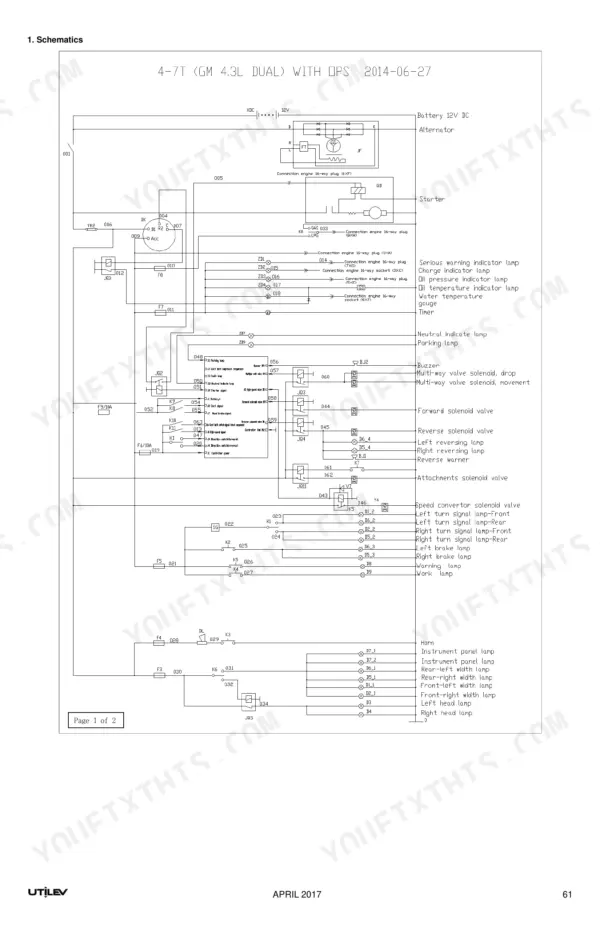
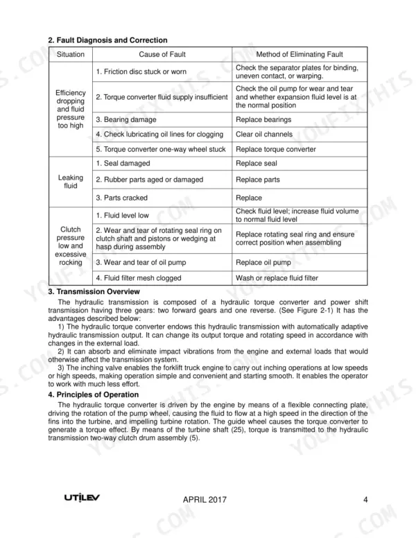
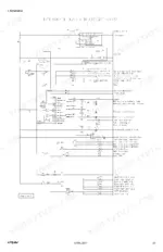
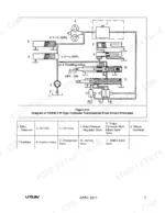
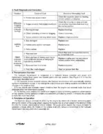
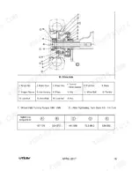
Issued by Utilev under factory document number 76500008, this 76-page Utilev UT40P, UT50PS, 4T-5TS service manual PDF is the real book for the 4T-5TS series of internal combustion counterbalanced forklift trucks, spanning six variants in dual-fuel, LPG and diesel builds. Electrical schematics trace the fuse box and lighting circuits wire by wire, while the hydraulic circuit diagram follows oil from the main pump through the control valve to the lift and tilt cylinders. Fault diagnosis tables open each system, from the torque converter and two-way clutch to the drive axle, steering axle, brakes and mast, and the lifting chapter walks you through dismantling, installing and adjusting the mast. Your transmission takes 12 L, and the fluid comes out every 1,000 hours on the meter. One missing figure can park a truck all shift. Chapter bookmarks and a searchable text layer put you on the brake master cylinder or steering control unit in seconds.
What's Inside This Manual
| System | Pages | Key Topics |
|---|
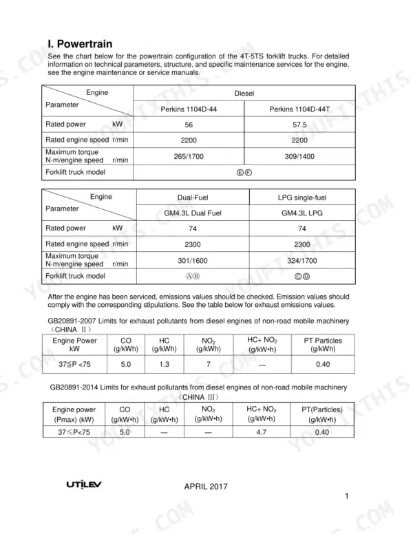
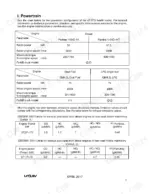
| Powertrain | 4-5 | Engine Configuration, Rated Power, Rated Engine Speed, Maximum Torque, Exhaust Emissions, Diagnostic Connector |
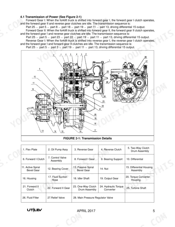
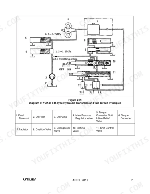
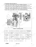
| Hydraulic Transmission and Torque Converter | 6-17 | Hydraulic Transmission Data, Fault Diagnosis and Correction, Transmission Overview |
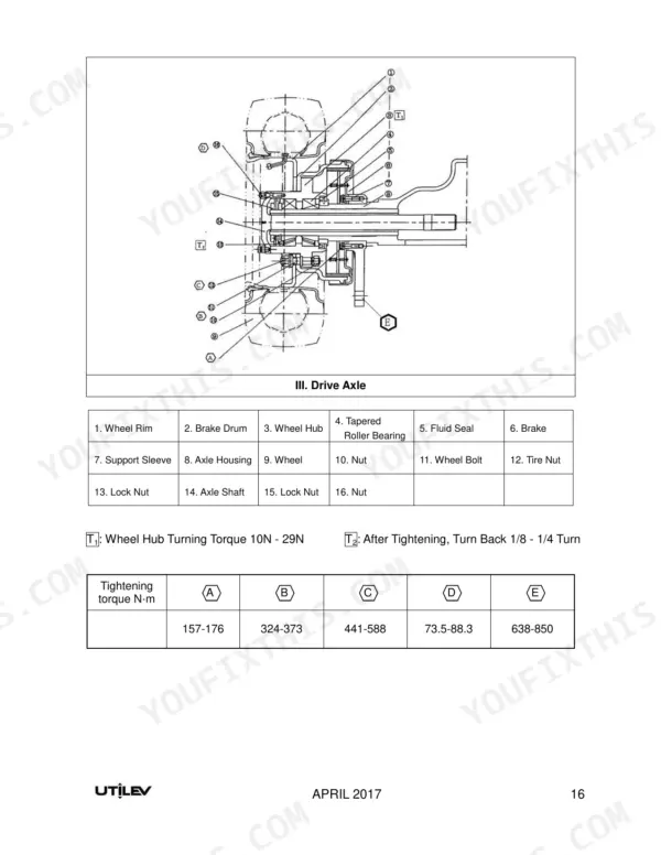
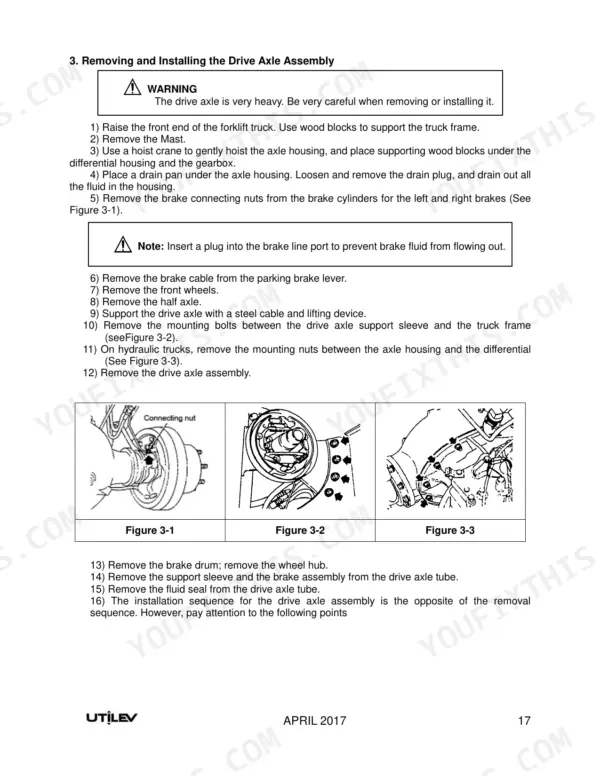
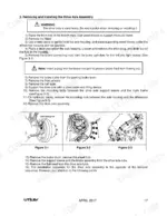
| Drive Axle | 18-22 | Data, Fault Diagnosis and Elimination (Removing and Installing the Drive Axle Assembly, Half Axle and Wheel Hubs, Bearings) |
| Steering Axle | 23-26 | Fault Diagnosis and Elimination (Steering Axle, Steering King Pin and Steering Spindle, Wheel Bearings) |
| Steering System | 27-30 | Steering System Troubleshooting, Hydraulic Steering Control Unit, Steering Cylinder |
| Brake System | 31-37 | Fault Diagnosis and Correction, Brake Master Cylinder, Brake Booster |
| Hydraulic System | 38-44 | Data, Fault Diagnosis and Correction (Main Oil Pump, Hydraulic Control Valve, Hydraulic System Circuit) |
| Lifting System | 45-56 | Assembly Data |
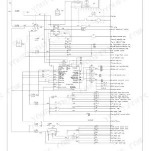
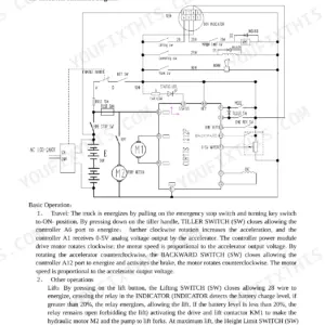
| Electrical System | 57-76 | Fuse Box Assembly, Lighting System, Removal and Installation |
Quick Reference Specifications
| Specification | Value | Page |
|---|
| Transmission Fluid Volume | 12 L | p. 6 |
| Transmission Fluid Replacement Interval | 1,000 hours | p. 9 |
| Tightening torque for wheel nuts (Tire Nut) | 638-850 N·m | p. 19 |
| Steering cylinder screw rod torque | 100 N·m - 120 N·m | p. 30 |
| Brake master cylinder piston-to-cylinder gap | 0.15 mm | p. 26 |
| Lift Chain Lock Nuts Torque | 441 ~ 539 N·m | p. 45 |
| Main Relief Valve Adjusted Pressure | 19 ± 0.25 MPa | p. 38 |
| Hydraulic Transmission Fluid Volume | 12L | p. 6 |
| Hydraulic Transmission Set Pressure | 1.2 MPa - 1.5 MPa | p. 6 |
| Drive Axle Tire Inflation Pressure | 830Pa | p. 18 |
| Steering Axle Tire Inflation Pressure | 0.86 MPa | p. 23 |
| Steering Cylinder Stroke | 181 mm | p. 27 |