
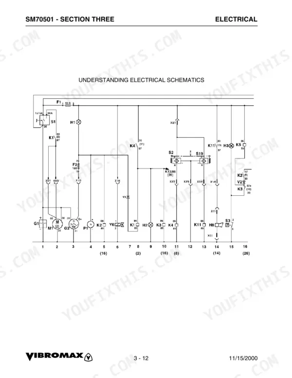
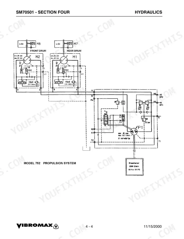
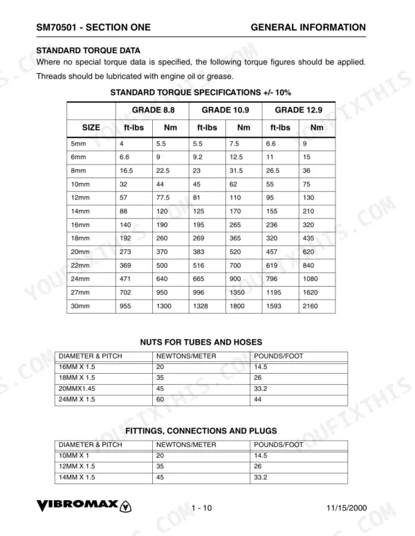
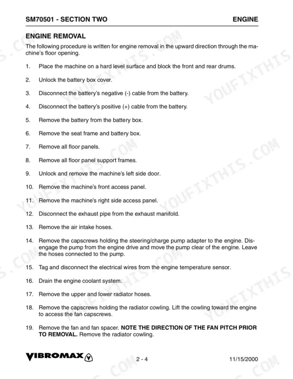
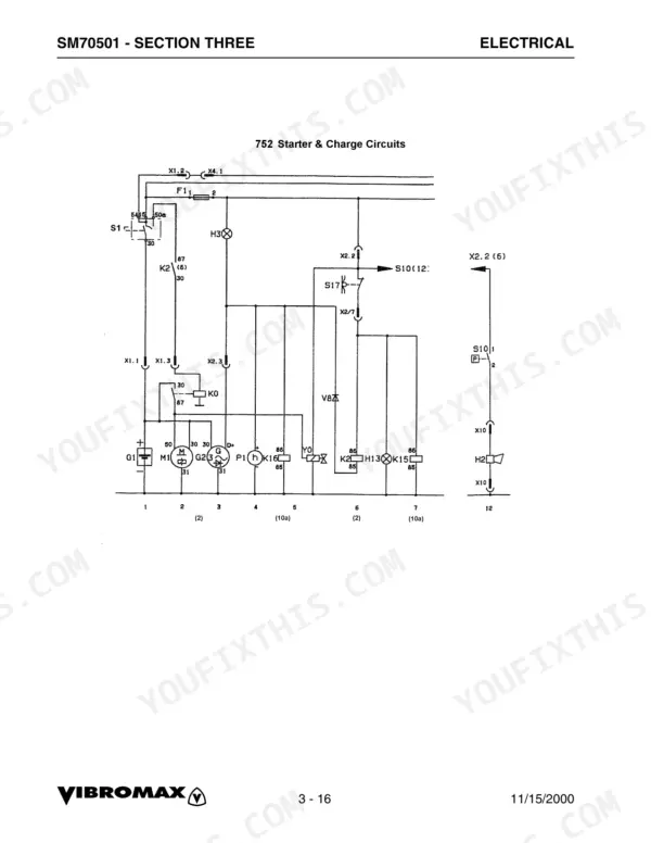
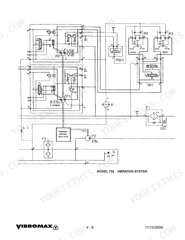
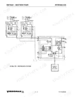
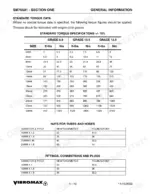
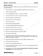
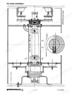
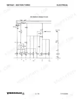
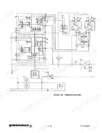
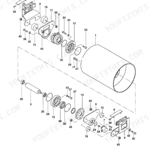
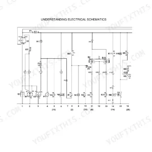
Engine, electrical, hydraulics, drum drive, parking brake, vibration, steering and chassis all run start to finish through this Vibromax 752 service manual PDF, publication SM70501, a 190-page shop book for the 752 tandem drum roller. Electrical work fills a big share of the book, with schematics for the starter, charging, lighting, water sprinkler and vibration control circuits plus wire charts for the right panel, left panel, front and rear harnesses, so you can trace a dead lamp back to its connector. Hydraulic schematics trace the propulsion, vibration, steering and brake circuits, and the pressure test points are laid out so you know where to tee in a gauge. Look for 18 to 30 bar of charge pressure at test point MP5, and torque a 20 mm x 1.45 tube nut to 45 Nm (33.2 ft-lbs). A roller with no vibration idles the whole paving crew. The bookmarked, text-searchable PDF travels on your laptop to wherever the 752 is parked.
What's Inside This Vibromax 752 Manual
| System | Pages | Key Topics |
|---|---|---|
| General Information | 7-30 | Machine Description, Machine Serial Numbers, Identifying Machine Components |
| Engine | 31-38 | Engine Data, Cummins Engine Warranty, Engine Removal |
| Electrical | 39-88 | Instrument Panel, Right, Left, Instrument Panel Cover, Combination Indicator |
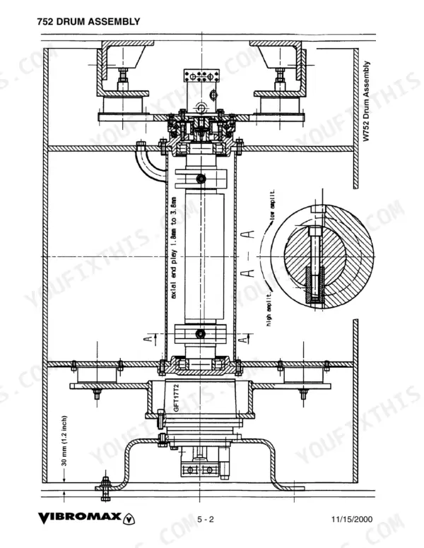
| Power Train | 113-130 | Drum Assembly, Drum Removal, Drum Installation, Drum Drive Bearing Removal, Drum Drive Bearing Assembly, Drum Drive Motor Repairs, Drum Drive Gearbox, GFT 17 T2/312 2 Gearbox |
| Parking Brake System | 131-138 | Brake Circuit, Towing Your Machine |
| Vibration System | 139-162 | Vibration System Overview, Vibration Amplitude, Vibratory System Diagnostics |
| Steering System | 163-174 | Steering System Overview, Steering Pivot Removal |
| Chassis | 175-184 | Rear Engine/Roller Frame, Front Roller Frame, Steering Link, Front Water/Diesel Tank, Rear Water/Hydraulic Tank, Instrument Console, Seat Rack, Rollover Protection Structure |
| Attachments | 185-190 |
Quick Reference Specifications
| Specification | Value | Page |
|---|---|---|
| Torque for Nuts for Tubes and Hoses (16mm x 1.5) | 20 Nm (14.5 ft-lbs) | p. 16 |
| Torque for Nuts for Tubes and Hoses (20mm x 1.45) | 45 Nm (33.2 ft-lbs) | p. 16 |
| MP5 Charge pressure | 18 to 30 bar | p. 110 |
| MP3 Vibration system pressure | 18 to 350 bar | p. 110 |
| MP4 Vibration system pressure | 18 to 350 bar | p. 110 |
| Gearbox oil capacity | 3.7 quarts (3.5 liter) | p. 128 |
| Drum drive bearing capscrew torque | 110 Nm (81 ft lbs) | p. 125 |
| Buffer support plate capscrew torque | 110 Nm (81 ft lbs) | p. 125 |
| Drum shaft axial end play | 1.8mm to 3.8mm | p. 126 |
| Drum weight | 6725 lbs (3050 kg) | p. 156 |
| Machine weight w/o drum & ROPS | 15545 lbs (7050 kg) | p. 156 |
| Machine weight w/o tank and Rops | 15545 lbs. (7050 Kg) | p. 169 |
Vibromax 752 Common Problems This Manual Covers
Vibromax 752 starter solenoid only clicks when the key switch is turned to the start position
Fasten the manual shut off lever on the injection pump in the OFF position before testing, as the caution on page 62 requires. Check for a poorly charged battery, corroded cables, a bad connection, poor ground or a bad solenoid. Measure from starter case to negative battery terminal with the key at start; over 0.5 volts means the starter is poorly grounded.
Manual Section: Starter System Diagnostics p. 62Starter solenoid test light stays off with the key switch held in the start position
Fasten the manual shut off lever on the injection pump in the OFF position, as the page 61 caution requires. Connect a test light or voltmeter between test point (1) and a good ground, then turn the key to start. No system voltage means a current supply problem to the solenoid. If supply is good but the starter terminal shows none, the solenoid is at fault.
Manual Section: Starter System Diagnostics p. 61Starter motor supply terminal reads outside 8.5 to 10.0 volts with key held at start
Fasten the manual lever on the fuel injection pump in the OFF position per the caution on page 63. Connect the positive voltmeter lead to the starter motor supply terminal and the negative lead to a good ground, then turn the key to start. A reading below 8.5 or above 10.0 volts points to the armature field or the brushes.
Manual Section: Starter System Diagnostics p. 63Alternator warning lamp on the instrument panel stays lit with key on and engine running
Check the lamp against the chart on page 58: lit with engine running means a regulator problem; dark with key on and engine off means a bad alternator diode. With engine off, measure B+ terminal to engine ground for 12 volts per page 59. At half throttle with lights on, V1 must not exceed 0.5 volts and V2 0.25 volts. Lock the articulation joint and never leave the machine running (page 28).
Manual Section: Charging System Diagnostics p. 58Battery goes flat while the machine sits parked with the key switch in OFF
Remove jewelry and watch bands before working on batteries, as page 28 warns. Remove the ground cable from the battery, turn the key switch OFF and connect a test lamp between the negative post and the cable following page 59. A lit lamp means a power source is going to ground. Load test the battery only at 80% charge or better per page 57.
Manual Section: Charging System Diagnostics p. 59Vibration system running at low frequency with the roller riding rough and bucking
Verify engine speed is at maximum rpm, then pressure test at test station taps #3 and #4 per page 148: start up may hit 350 bar (4977 psi) but should settle at 100 to 240 bar at operating speed. Check frequency with a frequency meter against 2000 vpm (33 Hz) and 3000 vpm (50 Hz). Lock the articulation joint and never leave the machine running (page 28).
Manual Section: Vibratory System Diagnostics p. 148Frequently Asked Questions
What causes a Vibromax 752 to lose vibration?
Vibration loss can be caused by the vibration frequency switch (S12) being in the OFF position, or by the vibration control switch (S11) being turned OFF. Additionally, if the machine is in neutral, the automatic vibration function will stop. Ensure the drum selection switch (S18, S19, or S20) is properly selected and that the vibration control switch (S11) is in the ON position. p. 42
What is the procedure to bleed the brake system on a Vibromax 752?
After installing the hydraulic hoses on the vibration and drive motors, start the engine and allow the hydraulic systems to develop charge pressure. Run the engine at low idle for several minutes to flush the system, then bleed the brake system at the brake ports as necessary. p. 122
What is the engine oil capacity for the Cummins 3.9 liter engine in the 752?
The engine crankcase capacity for the Cummins 3.9 liter engine is 11.5 quarts (10.9 liters). p. 18
What is the torque specification for the ROPS mounting bolts on the Vibromax 752 tandem drum roller?
The 16 bolts, nuts, and washers that secure the ROPS to the machine must be torqued to 195 foot pounds (265 Nm). p. 21
What are the valve clearance specifications for the Cummins engine on the Vibromax 752?
The inlet valve clearance (cold) is .010 inch (.25mm) and the exhaust valve clearance (cold) is .020 inch (.51mm). p. 32
What do I get after purchasing this Vibromax 752 manual?
Instant PDF download. You get the full 190-page searchable Service Manual immediately after payment. Open it on your laptop, tablet, or phone right in the shop.
Am I able to print pages from this Vibromax 752 manual?
Yes. Print the sections you need to take out to the shop for your own use. Standard letter or A4 paper works.


Reviews
There are no reviews yet.