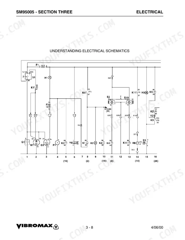
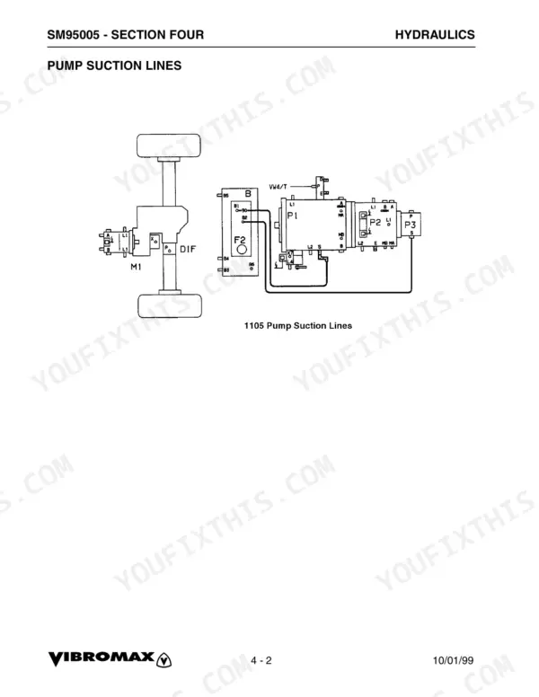
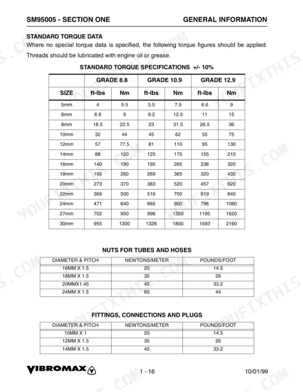
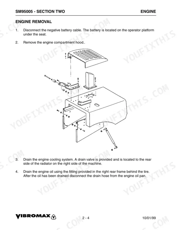
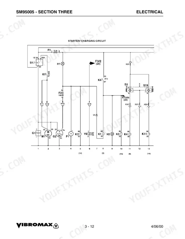
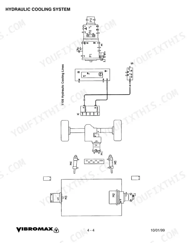
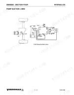
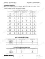
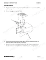
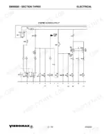
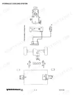
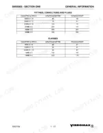
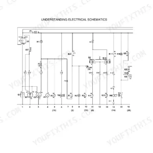
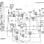
Ten chapters over 240 pages make this Vibromax 1105 service manual PDF (publication SM95005) a single factory reference for four single drum roller models in the 1105 family, from engine removal through drum exciter bearings. Starter and charging circuits are drawn separately for the Cummins 6B5.9C and 6BT5.9C engines, and wire charts list the leads of each harness, covering the vibration, high speed, lighting and cab circuits. On the hydraulic side, a full machine schematic maps suction, drain, charge and propulsion lines, while diagnostics cover internal leakage, pump servo control and the vibratory system. Set your test gauges for 20 bar (285 PSI) charge and 140 bar (2000 PSI) steering. Ordering a replacement wire harness 7241/80315 (0)? Its matching wire chart lets you confirm each circuit first. Bookmarks take you straight to the chapter you want, and the text layer finds any harness number in seconds, so download your copy and keep it with the roller.
What's Inside This Manual
| System | Pages | Key Topics |
|---|
| General Information | 9-42 | Machine Description, Safety General |
| Engine | 43-48 | Engine Data, Cummins Engine Warranty, Engine Removal |
| Electrical | 49-108 | Fuse Location, Relay Location, Instrument Panel, Understanding Electrical Schematics, Understanding Relays (Vibromax Relays), Starter/Charging Circuit |
| Power Train | 151-190 | Operation, Speth Axle, Rear Axle Removal, Rear Axle Installation, Axle Tube Disassembly, Planetary Dissassembly, Differential Lock Removal, Differential Lock Assembly |
| Parking Brake System | 191-198 | Description, Brake Release and Towing, Towing Procedure, Axle Brake (Parts List) |
| Vibration System | 199-212 | Vibration Frequency, Vibratory System Diagnostics |
| Steering System | 213-224 | Special Tools, Articulation Joints, Joint Disassembly, Joint Assembly, Steering Cylinder |
| Chassis | 225-230 | Drum Frame, Rear Frame, Hood, Operator Platform, Rollover Protection Structure |
| Attachments | 231-240 | Leveling Blade, Blade Control, Blade Hydraulic Lines |
Quick Reference Specifications
| Specification | Value | Page |
|---|
| Charge pressure | 20 bar (285 PSI) | p. 117 |
| Steering pressure | 140 bar (2000 PSI) | p. 117 |
| Start up pressure | 420 bar (6090 PSI) | p. 134 |
| Operating pressure | 100 to 150 bar (1400 to 2200 PSI) | p. 134 |
| Axle mounting bolts torque | 295 ft lbs. (400 Nm.) | p. 156 |
| Wheel lug nuts torque | 288 ft lbs. (390 Nm.) | p. 156 |
| Collar nut torque | 332 ft lbs (450 Nm) | p. 171 |
| Cover capscrews torque | 51 ft lbs (69 Nm) | p. 171 |
| M24x80 capscrews torque | 471 ft lbs (640 Nm) | p. 211 |
| Drive bearing housing capscrews (44) torque | 471 ft lbs (640 Nm) | p. 211 |
| Fuel Tank Capacity | 105 gal (397 ltr) | p. 15 |
| Hydraulic Reservoir Capacity | 18.5 gal (70 ltr) | p. 15 |