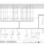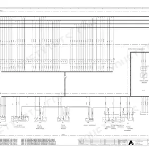
Questions about the 5005 MI industry machine's hydraulics, wiring and Kessler axle are settled in this 322-page Atlas 5005 MI workshop manual PDF, OEM ID 6037820. Electrical circuit diagrams trace the machine's wiring, and the hydraulic-circuit diagrams lay out the system plans. Repair guidance covers the A20VLO pump, the load-sensing control block, the shiftable hydraulic engines, the boom cylinder, the slewing rim, the transmission and the central lubrication, and the steering chapter lists its fault messages. The Deutz BF6M 1013CPFC EMR engine is listed at 7.15 L and 183 kW. When bleeding a cylinder under steering pressure, tighten the ventilation screw to 28 Nm once bubble-free oil emerges. If your next order is a replacement A20VLO pump or a Centaflex Type H, the exact designations are printed here for you to quote. The bookmarked, text-searchable PDF stays yours for as long as you run this 5005 MI.
What's Inside This Atlas 5005 MI Manual
| System | Pages | Key Topics |
|---|---|---|
| Introduction to the Hydraulics | 4-10 | General Information on Hydraulics |
| Technical Specifications | 11-19 | General Technical Specifications |
| Cabin | 20-35 | Overview of Cabin |
| Diesel Engine | 36-52 | Deutz EMR Control System |
| Pumps | 53-63 | Repair Guide Pump A20VLO |
| Control Block | 64-72 | Load-Sensing Control Block |
| Settings | 73-88 | Deaerate Installation |
| Hydraulic Engines | 89-104 | Shiftable Engine |
| Cylinder | 105-116 | Boom Cylinder |
| Hydraulic Accessories | 117-133 | Pipe-Shear Safeguard |
| Air-Conditioning System | 134-146 | Technical Data |
| Main Rotary Connection | 147-154 | Rotary Connection and Transmission |
| Ball-Bearing Slewing Rim | 155-160 | Lubrication and Maintenance |
| Transmission | 161-172 | Driving Gears |
| Kessler Axle | 173-235 | General Information |
| Steering | 236-250 | Fault Messages |
| Electrical Installation-Circuit Diagrams | 251-299 | Diagrams of the Electrical System |
| Hydraulic-Circuit Diagrams | 300-301 | Hydraulic System Plans |
| Maintenance | 302-317 | Central Lubrication |
| Miscellaneous | 318-322 | Centaflex Type H |
Quick Reference Specifications
| Specification | Value | Page |
|---|---|---|
| Ventilation of cylinders | 28 Nm | p. 132 |
| Pre-tension moment | 50 Nm (5kpm) | p. 160 |
| Engine BF6M 1013CPFC EMR Piston capacity | 7.15 L | p. 12 |
| Engine BF6M 1013CPFC EMR Performance | 183 kW | p. 12 |
| Main pump A20VLO max. operating pressure | 360 bar | p. 13 |
| Fan motor WM09A1C-230 max. pressure | 221 bar | p. 16 |
| Oil pump WP09A2C-160-110 max. pressure Stage 1 | 276 bar | p. 16 |
| Oil pump WP15A2C-190-280 max. pressure Stage 1 | 276 bar | p. 17 |
| Valve free-play Inlet valve (BF6M 1013FC) | 0.3 mm | p. 49 |
| Valve free-play Outlet valve (BF6M 1013FC) | 0.5 mm | p. 49 |
| Slewing motor A10FD max. moment of holding brake | 630 Nm | p. 170 |
Atlas 5005 MI Common Problems This Manual Covers
Atlas 5005 MI EMR engine control lamp 27 flashing with display fault No. 400 voltage too low
Check the input voltage reaching the EMR whenever control lamp 27 flashes and monitor view No. 400 shows Voltage too low, as laid out on page 41. Trace the EMR supply feed through the electrical circuit diagrams starting on page 251. Clear the supply fault first, then recheck for the EEPROM and memory faults (No. 401, No. 402) listed on page 42.
Manual Section: Deutz EMR Control System Fault Detection p. 41EMR actuator fault No. 404 or No. 405 with control lamp 27 flashing on the display
Inspect the EMR actuator and its cable routing following page 44. No. 404 points to the path measuring system on the actuator or its cable routing; No. 405 points to the actuator itself or the cable routing. Check the harness run against the electrical circuit diagrams from page 251 before replacing the actuator.
Manual Section: Deutz EMR Control System Fault Detection p. 44EMR coolant sensor fault No. 407 or engine cut-out system fault No. 406 shown on display
Check the coolant sensor and its cable routing when monitor view No. 407 appears, and inspect the engine cut-out system and its wiring for No. 406, both detailed on page 45. Lamp 27 flashes for either fault. Trace the circuits on the diagrams from page 251 and repair the out-of-order sensor, cut-out or cable run.
Manual Section: Deutz EMR Control System Fault Detection p. 45Steering fault message for proportional valve excitation, nominal value transmitter or position feedback error
Check the exact steering fault message against the fault message tables on pages 245 and 246. Verify proportional valve excitation, the steering nominal value transmitter and the position feedback signal, then work through any digital output or input errors listed for that message before replacing components.
Manual Section: Steering System Fault Messages p. 245Central lubrication pump not working, pump element delivering no lubricant, or pump running empty
Check whether the central lubrication pump functions at all, then verify each pump element is delivering lubricant and confirm the pump is not running empty. Inspect the system and distributor for blocking. Work each cause in order.
Manual Section: Central Lubrication TroubleshootingAxle block support effect decreasing with joint cross shaft axle stability problems
Check the axle block cylinders for trapped air and vent them following page 132. Apply steering pressure to the cylinder with the ventilation screw loosened, and tighten the ventilation screw to 28 Nm as soon as oil free of bubbles emerges. Repeat on each cylinder, then recheck support effect and axle stability.
Manual Section: Axle Block Troubleshooting p. 132Frequently Asked Questions
How do I clear the error memory on the Atlas 5005 MI steering computer?
To clear the error memory, open the error memory display status. Keep the '+' key pressed for 3 seconds until the prompt 'error memory clear?' appears. Press the enter key to confirm and start the clearing procedure, or press ESC to cancel. p. 249
What is the procedure for deaerating the hydraulic installation after a pump replacement?
Deaeration is required after pump replacement. Use compressed air through the connection (1) to assist. Detach the aeration screw (2) and tighten it again as soon as bubble-free hydraulic oil begins to flow off. p. 74
What is the correct valve free-play setting for the BF6M 1013FC engine in the Atlas 5005 MI?
For the BF6M 1013FC engine, the valve free-play at an oil temperature below 80°C should be 0.3 mm for the inlet valve and 0.5 mm for the outlet valve. After initial assembly or cylinder-head gasket replacement, these values change to 0.4 mm for the inlet and 0.6 mm for the outlet. p. 49
What is the tightening torque for the wheel fastening nut on the 111 model in the Atlas 5005 MI wheel bearing table?
In the wheel bearing setting table, the wheel fastening nut torque for the 111 model is 750 Nm. p. 218
What is the fuel pressure requirement for the Atlas 5005 MI BF6M 1013FC engine during zero-load operation?
For the BF6M 1013FC engine, the minimum fuel pressure during zero-load operation is 4.2 bars for a rotary speed range between 1500 min-1 and 1900 min-1, and 5 bars for a range between 1900 min-1 and 2300 min-1. p. 52
Is this Atlas 5005 MI manual a PDF I download?
Straight to your device: 322 pages of searchable Workshop Manual, downloadable the moment payment goes through.
Does this Atlas 5005 MI manual allow printing?
You can. Print the sections you want for your own use and keep the file as your backup.