Need the complete Terex Atlas 282, 283, 284, 372, 373, 374, 935, 1704, 1804 workshop manual PDF? These 457 factory pages (OEM #7800.715.20.06/000) cover the full backhoe and industrial rehandler line, mobile and tracked variants alike. You get electrical construction and flow drawings for both the 1996 and 1999 systems, separate hydraulic schematics for the 372/282, 373/283, and 374/284 series, plus Deutz engine adjustment procedures and Quicklub central lubrication service. Inside: CEB 10/40 excavator control adjusting instructions, air bleeding steps, welding repair sequences with filler metal selection, and a hydraulics theory section that explains what those testpoints actually measure. Set fuel pressure to 1.1 bar, hold control pressure delta-P at 0.7 bar, and torque each pump element to 30-35 Nm. Your rehandler is down and the dealer wants a week. Bookmarked and keyword-searchable; jump straight to the schematic and start wrenching.
What's Inside This Manual
| System | Pages | Key Topics |
|---|
| 935 Operators Cabin | 4-26 | General View of Cabin, Right Hand Switch Panel, Left Hand Switch Panel, Multifunction Levers, Adjustable Steering Column, Displays and Controls |
| Deutz Engine | 27-30 | Measurement of Fuel Pressure, Special Adjusting Instructions, Tappet Adjustment Procedure, Valve Clearance, Minimum Engine Revolution Adjustment, Engine Speed Control Lever |
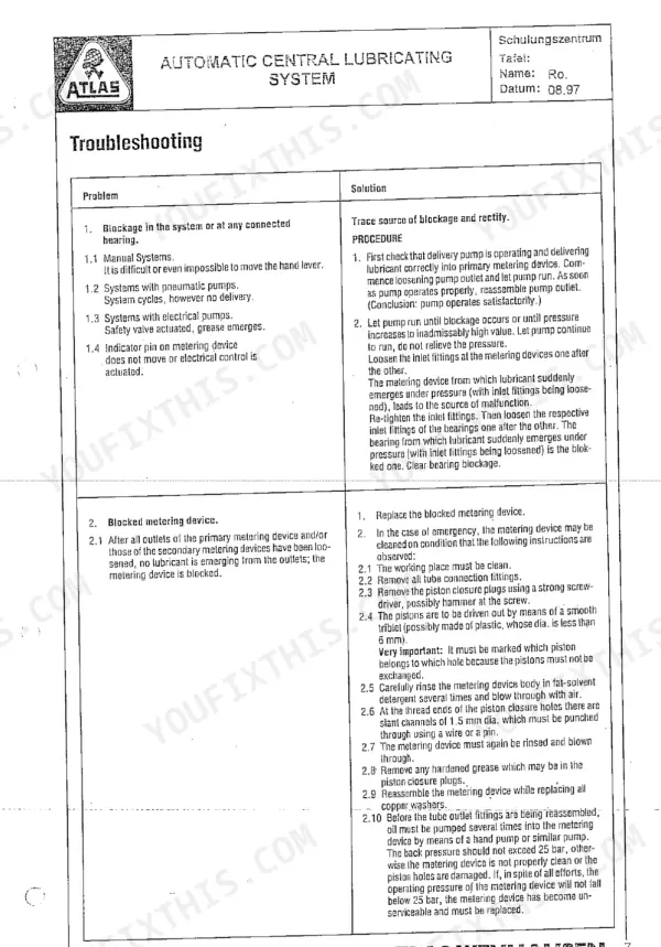
| Lubrication | 31-42 | Automatic Central Lubrication System, Quicklub Pump Components, "Progressive" Plunger Metering Device, Crossporting of Outlets, Pump Element Exchange, Ball Slew Ring Lubrication |
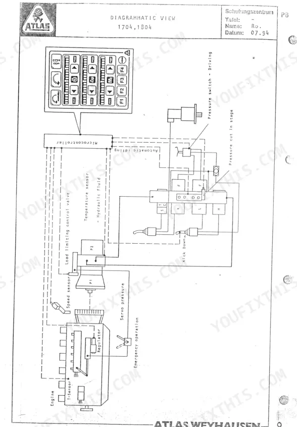
| 1704/1804 - 372/282 Series | 43-106 | Electronic Operating Panel, Engine Speed Sensor Adjustment, Engine |
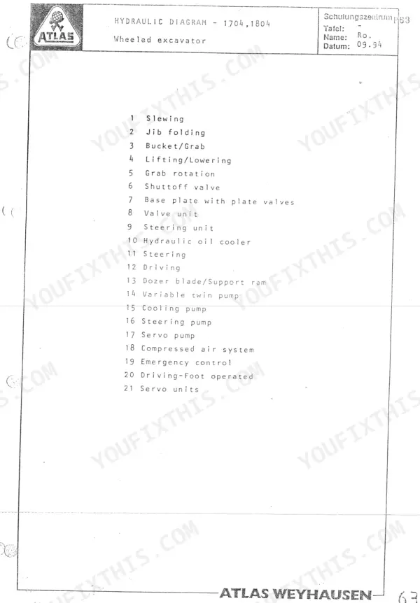
| Hydraulic Diagram 372,282 | 107-110 | |
| 1704/1804 - 373/283 Series | 111-187 | |
| Hydraulic Diagram 373,283 | 188-195 | |
| 1704/1804 - 374/284 Series | 196-263 | |
| Hydraulic Diagram 374,284 | 264-277 | Shuttle Valve Unit, Plate Valve, Primary Valve Ls Controlled, Pressure Cut-Off Valve, Pressure Cut-In Stage, Slewing Motor |
| Welding | 278-284 | Doubler of Metal Sheet, Preparing the Repair, Preheating the Welding Area, Qualified Welders, Selecting the Filler Metal, Repair Sequence |
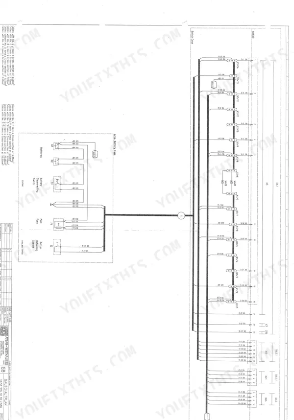
| Electric - Electronic | 285-392 | El. Construction Drawing 1996, El. Flow Drawing 1996, Boards 1 - 4 ( New ), El. Construction Drawing 1999 |
| Theory | 393-411 | Nature and Uses of Hydraulics, Hydraulics Terms, Hydraulic Equipment for Conversion of Energy, Hydraulic Pumps, Control Valves, Relief and Safety Valves |
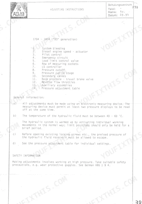
| Adjusting Instructions - Series 374/284 | 412-455 | Instructions, Bleeding Air From the System, Ceb 10/40 Excavator Control, Ceb 10_40 Com Iii, Pilot Control, Emergency Circuit, Load Limit Control Valve, Testpoints |
| Hydraulic Diagram - 1804 Mi Lift | 456 | |
| Hydraulic Diagram - 1804 Mi Variokabine | 457 | |
Quick Reference Specifications
| Specification | Value | Page |
|---|
| All Models |
| Hydraulic pilot control circuit shutdown | 26 | p. 6 |
| GLR - power limit controlled system (1704-2004) | off | p. 26 |
| Measurement of fuel pressure | 1.1bar | p. 28 |
| Pump element tightening torque | 30 - 35 Nm | p. 39 |
| Control pressure (delta-P) | 0.7 bar | p. 117 |
| Pilot control pressure - travelling - wheeled Checking/adjustment | 24 bar | p. 167 |
| Tightening torque for cylinder-head screws pos. 9 | 16 Nm | p. 247 |
| Unplug the Linde Load Limit Control Computer (LLC) | Twist the ring approx., 1¼ turn to loosen and pull the plug. | p. 278 |
| Fuel pre-pressure (Max. engine speed off-load) | 5 bar | p. 417 |
| Fuel pre-pressure (Min. engine speed off-load) | 2 bar | p. 417 |
| 1704 Series 374 |
| Diesel engine output, 1704 Series 374 | 122 KW at 2000 rpm | p. 204 |
| 1804 Series 284 |
| Diesel engine output, 1804 Series 284 | 161 KW at 1900 rpm | p. 205 |