
Part of the Case IH Repair Manuals.
Strip, test and put back together the Case IH Farmlift 633, 636, 737, 742 and 935 Stage IV telehandlers with factory service manual 51546954, dated 28/11/2018. It covers the NEF 4 Tier 4B engine, the powershift transmission, both axles, brakes, boom hydraulics, steering, the cab and the SCR/AdBlue aftertreatment.
Every day a telehandler sits with an amber light or a derated engine is a day of pallets and bales not moved. The fault code procedures for the ECU, TCU, UCM and ADIC, the relief pressures and the capacities are what get it back on the yard.
Print the sections you need and take them to the bench. They can get oily there, and the book on the shelf stays clean.
What's Inside This Case IH Farmlift 633–935 Manual
| System | Pages | Key Topics |
|---|---|---|
| Introduction (Safety, Basic Instructions, Torque, Consumables) | 1-62 | Safety Rules, Shop and Assembly Instructions, Electrical Equipment Precautions, Torque Tables, Hydraulic Contamination, Consumables and Capacities |
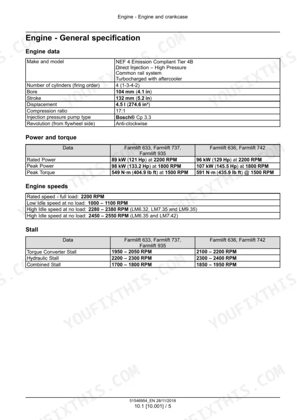
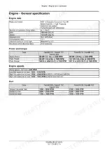
| Engine and Crankcase (10.001) | 63-92 | NEF 4 Tier 4B Engine General Specification, Power, Torque, Engine Speeds and Stall Speeds |
| Fuel Tanks, Fuel Filters and Air Cleaners (10.216, 10.206, 10.202) | 93-118 | Fuel Tank, Fuel Filters, Air Cleaner and Air Intake Lines |
| Selective Catalytic Reduction (SCR) Exhaust Treatment (10.500) | 119-156 | SCR Exhaust Aftertreatment Components, DEF/AdBlue System Service |
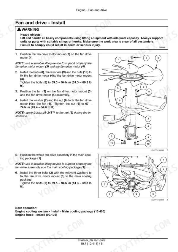
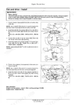
| Engine Cooling System, Fan and Drive (10.400, 10.414) | 157-182 | Radiator and Cooling System, Fan and Fan Drive Removal and Installation |
| Powershift Transmission (21.113) | 183-272 | Powershift Transmission General Specification, Hydraulic Schema, Removal and Installation |
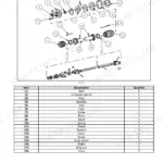
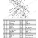
| Transmission Controls and Internal Components (21.135, 21.155) | 273-338 | Powershift Transmission External Controls, Internal Components Service |
| Gearbox, Transmission Cooler and Torque Converter (21.120, 21.109, 21.700) | 339-386 | Gearbox, Transmission Cooler and Lines, Torque Converter |
| Four-Wheel Drive (4WD) System (23.314) | 387-404 | Drive Shafts |
| Front Axle System (25.100-25.108) | 405-496 | Powered Front Axle, Front Bevel Gear Set and Differential, Final Drive Hub, Steering Knuckles and Shafts |
| Rear Axle System (27.100-27.124) | 497-566 | Powered Rear Axle, Rear Bevel Gear Set and Differential, Planetary and Final Drives, Final Drive Hub and Steering Knuckles |
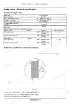
| Brakes and Controls (33.202-33.204) | 567-660 | Hydraulic Service Brakes, Parking Brake, Trailer Brake Hydraulic Control, Front Axle Brake |
| Hydraulic Systems and Pumps (35.000-35.106) | 661-694 | Hydraulic System General Specification and Hydraulic Schemas, Fixed Displacement Gear Pump, Variable Displacement Pump |
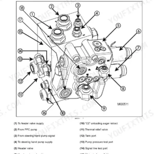
| Main Control Valve, Pilot and Auxiliary Hydraulics (35.359-35.752) | 695-750 | Main Control Valve, Pilot System and Accumulator, Auxiliary Hydraulic Function Control, Hydraulic Fan Drive Cooling System |
| Boom, Loader Arm and Quick Coupler Hydraulics (35.100-35.740) | 751-940 | Main Lift System, Hydraulic Hand Control, Front Loader Arm, Boom and Lock Valves, Tool Quick Coupler, Telescopic Arm Hydraulic System |
| Steering (41.101-41.216) | 941-988 | Steering Control General Specification, Hydraulic Control Components, Steering Cylinders, Wheel Alignment |
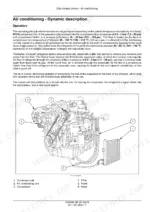
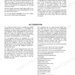
| Cab Climate Control (50.200) | 989-1056 | Air Conditioning Overview, Dynamic Description, Service |
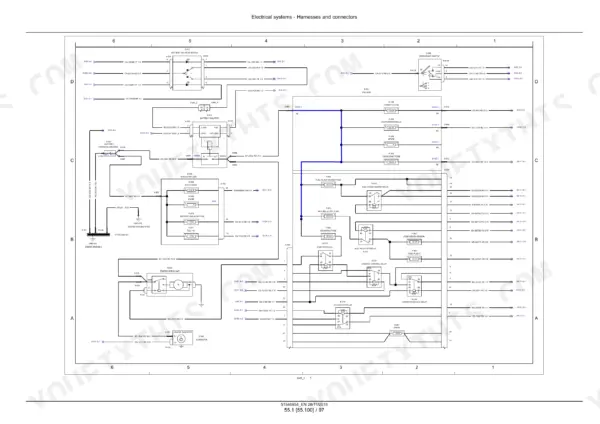
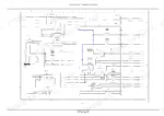
| Electrical Harnesses, Connectors and Schematics (55.100) | 1057-1880 | ECU and Sensor Descriptions, Electrical Schematic Sheets, Harness Connectors |
| Starting System, Battery, SCR Electrical and Steering Control (55.201-55.047) | 1881-1944 | Engine Starter, Battery, SCR Electrical System, Steering Control System |
| Warning Indicators, Calibration and Fault Codes (55.408) | 1945-3124 | Load Moment Calibration Procedures, Fault Codes (DTC) for ECU, Tcu, UCM and ADIC with Diagnostic Procedures |
| Telescopic Arm (83.122) | 3125-3142 | Quick Coupler Component Identification, Boom Pads Overhaul |
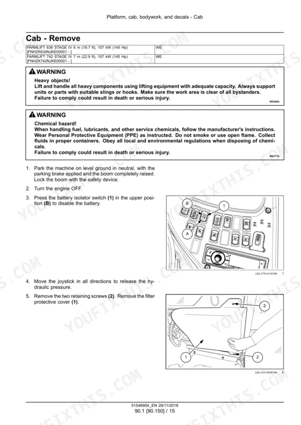
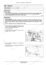
| Cab, Hood and Guards (90.150-90.105) | 3143-3191 | Cab Removal and Installation, Engine Hood and Panels, Machine Shields and Guards, Special Tool Index |
Quick Reference Specifications
| Specification | Value | Page |
|---|---|---|
| Engine | NEF 4 Tier 4B, 4 cylinders (1-3-4-2) | p. 68 |
| Engine bore | 104 mm (4.1 in) | p. 68 |
| Engine stroke | 132 mm (5.2 in) | p. 68 |
| Engine displacement | 4.5 l (274.6 in³) | p. 68 |
| Compression ratio | 17:1 | p. 68 |
| Rated power | 89 kW (121 Hp) at 2200 RPM (Farmlift 633, 737, 935); 96 kW (129 Hp) at 2200 RPM (Farmlift 636, 742) | p. 68 |
| Peak torque | 549 N·m (404.9 lb ft) at 1500 RPM (Farmlift 633, 737, 935); 591 N·m (435.9 lb ft) at 1500 RPM (Farmlift 636, 742) | p. 68 |
| Engine low idle | 1000 - 1100 RPM | p. 68 |
| Engine oil capacity with filter change | 12 l (3.2 US gal) | p. 43 |
| Cooling system capacity | 21 L (5.5 US gal) | p. 43 |
| Fuel system capacity | 138 L (36.5 US gal) | p. 43 |
| Hydraulic total system capacity | 157 L (41.5 US gal) | p. 43 |
| Transmission total system capacity (main housing and transfer box) | 21.45 L (5.67 US gal) | p. 43 |
| Front and rear axle oil capacity | 8 L (2.1 US gal) | p. 43 |
| DEF/AdBlue tank capacity | 32 l (8.4 US gal) | p. 43 |
| Hydraulic filter change interval | 500 h | p. 662 |
| Hydraulic oil change interval | 2000 h or every two years | p. 662 |
| Boom function main relief pressure | 236.5 - 243.5 bar | p. 663 |
| Steering shock pressure | 235 - 245 bar | p. 663 |
| Steering relief valve setting | 170 - 178 bar (2465 - 2581 psi) | p. 942 |
Case IH Farmlift 633–935 Common Problems This Manual Covers
Engine goes into reduced power, linked to DEF/AdBlue or a NOx sensor fault
The engine derates when DEF/AdBlue is not injected or has been contaminated. The fluid also freezes at -11 °C (12 °F) and breaks down in heat, so check its condition first. If fault 9582 (DTC 256E) is logged for the upstream NOx sensor, fix it. Then run the SCR Fault Repair Verification Test and do the Engine Restart Counter Reset / Unlock Inducement with the EST.
Manual Section: Selective Catalytic Reduction (SCR) exhaust treatment (10.500) - Control System Sensors p. 129Fault 4371 (DTC 1113), engine coolant temperature sensor voltage higher than expected
The ECU has seen more than 4.93 V on the coolant temperature sensor signal circuit. Use a multimeter to check that circuit for an open, a short, and a short to key battery power. If the wiring checks out, replace the sensor. If the fault is still there, check the ECU software and re-flash it if needed.
Manual Section: Fault codes (55.DTC) - 4371 - (DTC 1113) - Engine coolant temperature sensor voltage is higher than expected p. 2010Transmission will not engage a gear in extreme cold, fault 127-7 with the amber light on
Fault 127-7 is listed for the Farmlift 633, 737 and 935. It warns of frozen transmission oil. It sets when the engine is running, oil is below -15 °C and the Kprop solenoid is energized with no pressure for over 10 s. Gear engagement stays blocked until the fault clears. Use the EST to look for related transmission temperature faults.
Manual Section: Fault codes (55.DTC) - 127-7 - Side Drive Transmission - Warning for freezed transmission oil due to extreme cold conditions p. 2185Air conditioning compressor does not work
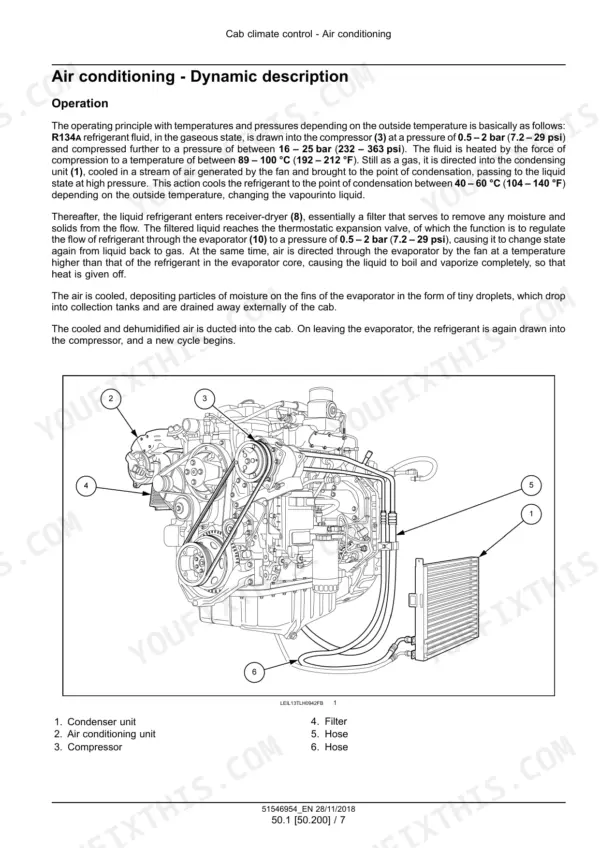
Check belt tension first and adjust it if the compressor belt is slack. Oil on the magnetic clutch friction linings means you clean or replace the clutch. Check the pressure switch, thermostat and relay for continuity, along with the ground connection and battery voltage. If all of those pass, the compressor itself is faulty and needs replacing.
Manual Section: Air conditioning (50.200) - Service instruction - Troubleshooting p. 1006Frequently Asked Questions
What are the fluid capacities of the Case IH Farmlift telescopic handlers?
Engine oil is CASE IH AKCELA UNITEK 10W-40, 12 l (3.2 US gal) with a filter change. The cooling system takes 21 L (5.5 US gal) and the fuel system 138 L (36.5 US gal). Hydraulic oil is AKCELA NEXPLORE FLUID, 157 L (41.5 US gal) total system. The transmission takes 21.45 L (5.67 US gal) across the main housing and transfer box. Front and rear axles take 8 L (2.1 US gal) and the DEF/AdBlue tank holds 32 l (8.4 US gal). p. 43
What engine is in the Farmlift 633 to 935 and what power does it make?
Every model runs the NEF 4 Tier 4B, a common rail, turbocharged and aftercooled four cylinder with 1-3-4-2 firing order. Bore is 104 mm (4.1 in), stroke 132 mm (5.2 in), displacement 4.5 l (274.6 in³) and compression 17:1. The 633, 737 and 935 make 89 kW (121 Hp) at 2200 RPM and 549 N·m (404.9 lb ft) at 1500 RPM. The 636 and 742 make 96 kW (129 Hp) at 2200 RPM and 591 N·m (435.9 lb ft) at 1500 RPM. Low idle is 1000 to 1100 RPM. p. 68
How do I reset the engine restart counter after an SCR inducement fault?
Fix the root fault first. Fault 9582 (DTC 256E), an internal failure of the upstream NOx sensor, is one that triggers inducement. Once it is resolved, run the SCR Fault Repair Verification Test. Then perform the Engine Restart Counter Reset / Unlock Inducement configuration with the Electronic Service Tool (EST) before the machine goes back to work. p. 2121
How do I test and bleed the service brakes on a Farmlift?
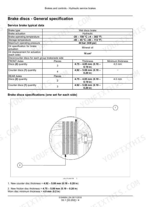
Connect a pressure gauge to the T-fitting on the front axle and press the brake pedal. You should see 40 bar (580 psi). If it reads low, look for leaks, then repeat the test at the rear axle. Bleed the system afterwards with two people. One holds the pedal down while the other opens the bleed screw until air or oil runs through a clear hose. Tighten the screw to 12 N·m (8.9 lb ft) with the pedal still held, then release the pedal and top up the reservoir. p. 591
What are the boom and steering relief pressures?
Boom function main relief is 236.5 to 243.5 bar. Steering shock pressure is 235 to 245 bar. The steering relief valve is set at 170 to 178 bar (2465 to 2581 psi). p. 663





Reviews
There are no reviews yet.