
Part of the Case IH Repair Manuals.
The hydrostatic drive is where a combine owner usually gets stuck, and this factory Case IH manual for the 2566, 2688 and 2799 covers it in full. It includes the hydrostatic drive schematic, pump, transmission, final drives, PTO and brakes. You also get the charge pump output and Foot-N-Inch valve pressure to test against.
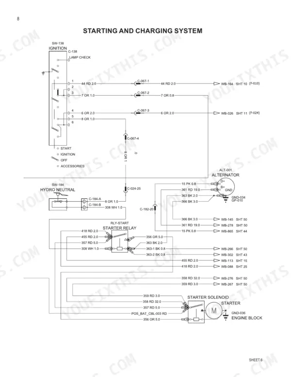
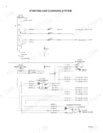
Past the driveline, it covers the main valve block, feeder reverser, reel drive valve and motor, rotor gearbox, feeder housing, unloader, chopper and concave adjustment. Section 3000 lays out the electrical schematics circuit by circuit, from starting and charging to header height/tilt and CAN bus.
Every day the combine sits in the shed, the crop stands in the field waiting on you. Pin the fault to one component, order the right part the first time and get back to cutting.
What's Inside This Case IH 2566, 2688, 2799 Manual
| System | Pages | Key Topics |
|---|---|---|
| Standard Torque Specifications and Fluids (1000-1010) | 1-11 | Torque Charts for Decimal and Metric Fasteners and Steel Hydraulic Fittings, Fluids, Lubricants and Capacities |
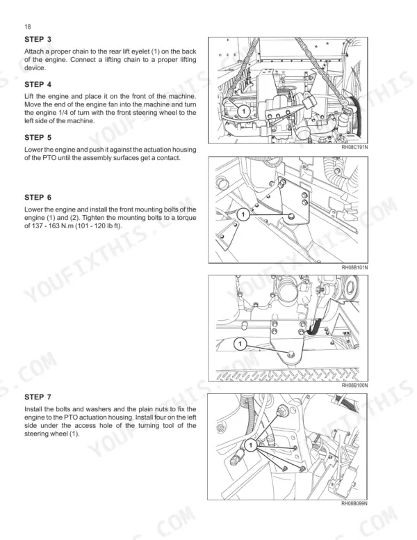
| Engine Removal and Installation (2000) | 12-43 | Engine Removal and Installation, Engine Mounting |
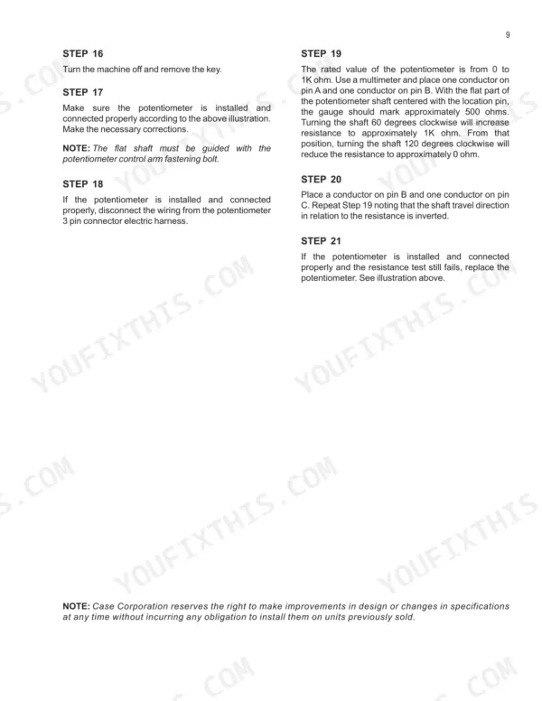
| Electrical Schematic and Electrical System (3000-3030) | 44-229 | Electrical Schematic, Connector Pin Information, Electrical System Troubleshooting, Neutral Start Switch, Starting with Auxiliary Batteries, Alternator |
| Steering (4000-4020) | 230-263 | Steering Hand Pump, Steering Cylinders, Steering Priority Valve |
| Rear Axles (5000-5020) | 264-369 | Rear Steering Axle, Axle with Auxiliary Traction, Power Guide Axle |
| Hydrostatic System (6000-6050) | 370-525 | Hydrostatic System Operation and Specifications, Hydrostatic Drive Schematic, Hydrostatic Drive, Drive System Testing, Slow Approach Valve, Hydrostatic Pump, Hydrostatic Motor and Transmission |
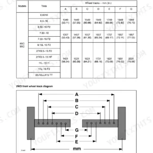
| Transmission and Final Drives (6060-6080) | 526-617 | Transmission Service, Standard and Heavy Duty Final Drives Removal and Overhaul, Wheel Spacing and Final Drive Position |
| PTO (7000-7020) | 618-677 | PTO Operation, PTO Gearbox Removal and Installation, Servicing the PTO Housing |
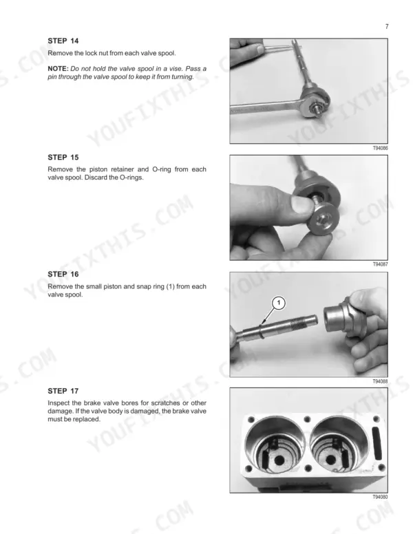
| Brakes (8000-8010) | 678-711 | Brake Assemblies Removal and Overhaul, Master Brake Valve |
| Hydraulic System Operation (9000) | 712-843 | Basic Principles, Hydraulic Pumps and Drive System, Steering Circuit, Main Valve Assembly and Solenoid Functions, Reel, Unloader and Field Tracker Valves, Accumulator, Service Brake Valve, Separator Drive, Pressure Tests |
| Feeder Reverser and Hydraulic Troubleshooting (9010-9020) | 844-895 | Feeder Hydraulic Reversor Drive, Hydraulic System Specifications, Troubleshooting Procedures, Pressure and Flow Tests |
| Hydraulic Valves and Pumps (9030-9070) | 896-979 | Pressure Regulator Valve, Auxiliary Gear Pump and PFC Pump, Main Hydraulic Valve Block, Parking Brake and Feeder Drive Valve, Separator Drive and Unloader Auger Drive Valves |
| Separator Drive, Air Screen, Cylinders and Reel Drive (9080-9120) | 980-1059 | Separator Drive Tests, Rotating Air Screen, Hydraulic Cylinders, Reel Drive Valve and Motor |
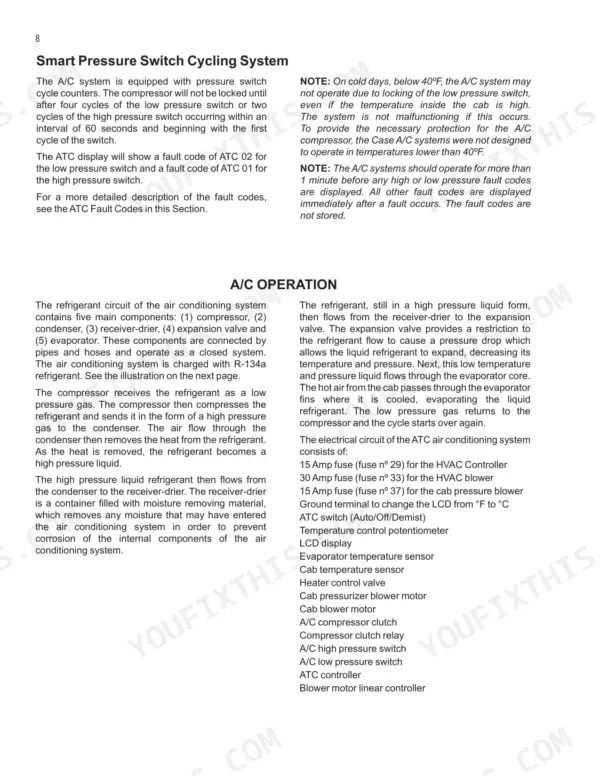
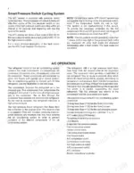
| Air Conditioning and HVAC (10000-10010) | 1060-1163 | Air Conditioning Troubleshooting, Automatic Temperature Control, HVAC System Repair |
| Separator and Rotor Drives (10020-10060) | 1164-1317 | Separator Drive Jackshaft, Rotor Drive, Rotor Gearbox, Rotor and Feeder Housing Removal, Rotor Drive Belt |
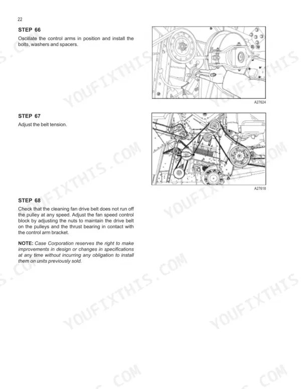
| Feeder, Cleaning Fan and Elevator Drives (10070-10090) | 1318-1381 | Feeder and Cleaning Fan Gearbox, Cleaning Fan Drive, Elevator Drive Jackshaft |
| Residue Handling (10100-10120) | 1382-1429 | Discharge Beater, Straw Spreader Drive, Blade Box |
| Tailings Monitor, Unloader, Engine Covering and Straw Chopper (10130-10160) | 1430-1495 | Tailings Monitor, Unloader System, Engine Covering, Straw Chopper Gearbox |
| Concave Adjustment and Cleaning System (10170-10180) | 1496-1569 | Concave Adjustment, Cleaning System Overhaul |
Quick Reference Specifications
| Specification | Value | Page |
|---|---|---|
| All Models | ||
| Engine oil type | CASE No. 1 SAE 15W-140 API CI-4 Engine Oil | p. 10 |
| Engine oil capacity | 19 Liters (20.1 U.S. Quarts) without filter change; 21 Liters (22.2 U.S. Quarts) with filter change | p. 10 |
| Coolant capacity (50% water and ethylene glycol) | 37.1 Liters (39.2 U.S. Quarts) | p. 10 |
| Transmission oil capacity (Case IH Hy-Tran Ultra) | 16.3 Liters (17.2 U.S. Quarts) | p. 10 |
| Final drive oil capacity | 12.3 Liters (13 U.S. Quarts) | p. 10 |
| Hydrostatic charge pump output, grain | 12 GPM (45.5 L/min) | p. 372 |
| Foot-N-Inch valve pressure, corn and grain | 6450±50 psi (444 bar) | p. 372 |
| PFC piston pump output to the camshaft (2700 engine RPM, oil 100 °F / 38 °C or higher) | 16.5 GPM (62.4 L/min) minimum | p. 866 |
| Field Tracker relief valve pressure set point | 207 Bar (3000 psi) | p. 916 |
| Wheel bolt torque | 275 lb ft (374 Nm) with a light application of oil | p. 587 |
| Engine front mounting bolt torque | 137 - 163 N.m (101 - 120 lb ft) | p. 29 |
| Final drive mounting bolt torque, standard and heavy duty | 375 to 400 lb ft (508 to 542 Nm) | p. 587 |
| 2566 | ||
| Fuel tank capacity, 2566 | 492 Liters (130 U.S. Gallons) | p. 10 |
| Hydraulic reservoir capacity, 2566 | 35.3 Liters (37.3 U.S. Quarts) | p. 10 |
| PTO case oil capacity, 2566 | 10.4 Liters (11 U.S. Quarts) | p. 11 |
| A/C refrigerant capacity, 2566 | 2.94 Kg (6.5 Lbs) | p. 11 |
| 2688, 2799 | ||
| Fuel tank capacity, 2688 / 2799 | 645 Liters (170 U.S. Gallons) | p. 10 |
| PTO case oil capacity, 2688 / 2799 | 13.2 Liters (14 U.S. Quarts) | p. 11 |
| A/C refrigerant capacity, 2688 / 2799 | 2.21 Kg (4.88 Lbs) | p. 11 |
| Rotor front bearing housing to impeller blade clearance, 2688 / 2799 | 0.76 to 3.81 mm (0.03 to 0.15 inches) | p. 1260 |
Case IH 2566, 2688, 2799 Common Problems This Manual Covers
Separator clutch does not activate
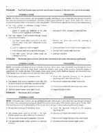
Check the oil level in the separator clutch housing first and top it up as needed. Next, run the machine at high revolution and look at the visual indicator on the suction filter housing. Replace the element if it shows clogging, because that starves the clutch of pressure. If oil and filter check out, confirm the separator clutch solenoid valve is getting power.
Manual Section: Hydraulic Troubleshooting and Diagrams (9020) - Separator Clutch p. 876Reel does not turn
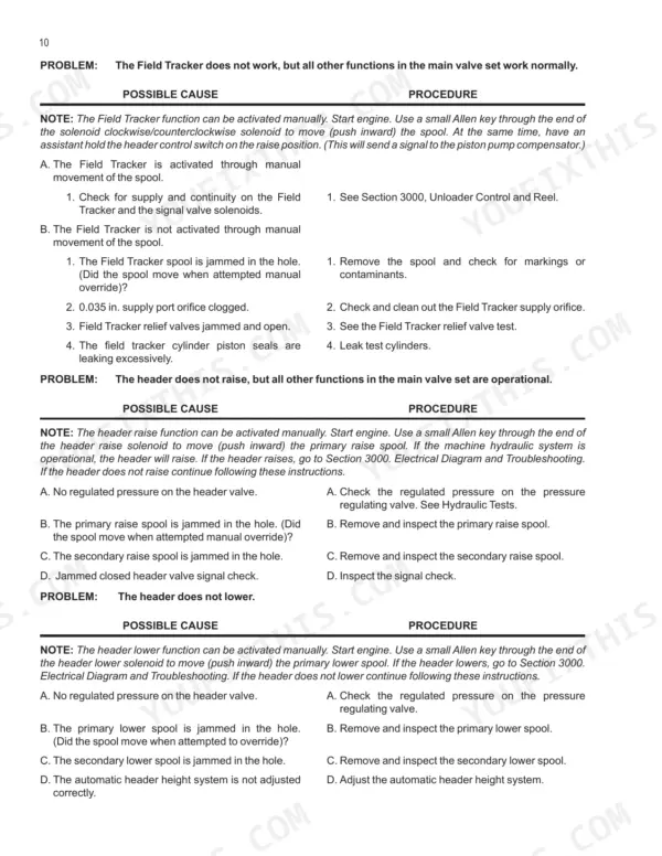
The reel drive valve can be worked by hand. Start the engine and engage the feeder and separator. Then push a small Allen key through the end of the reel drive solenoid to move the pilot spool inward. If the reel turns now, the hydraulics are fine and the fault is electrical, so go to the Section 3000 electrical diagrams and troubleshooting.
Manual Section: Hydraulic Troubleshooting and Diagrams (9020) - Gear Pump Circuit p. 875Hydrostatic system running hot
Check the return filter. When it clogs, return oil gets routed away from the cooling circuit and the hydrostatic system runs hot. Change the oil and filters every 1,000 hours, and any time you replace a major component.
Manual Section: Hydrostatic System (6000) - Return Filter p. 376Header or reel function does not work (electrical or hydraulic fault)
Each solenoid has a pin in its center that you can push by hand if the solenoid circuit fails. If the function works when you push the pin, the hydraulic side is doing its job and the problem is electrical. If it still won't move, stay on the hydraulic side and work through the troubleshooting and pressure tests.
Manual Section: Hydraulic System Operation (9000) - Main Valve Assembly Solenoid Functions p. 742Frequently Asked Questions
What is the wheel bolt torque on the Case IH 2566, 2688 and 2799 combines?
Wheel bolts go to 275 lb ft (374 Nm) with a light application of oil. If you have the final drive off, its mounting bolts take 375 to 400 lb ft (508 to 542 Nm) on both the standard and heavy duty versions. p. 587
How much engine oil does the Case IH 2566, 2688 or 2799 take?
The book calls for CASE No. 1 SAE 15W-140 API CI-4 Engine Oil. Plan on 19 Liters (20.1 U.S. Quarts) without a filter change, or 21 Liters (22.2 U.S. Quarts) with a new filter. p. 10
How do I reset an ATC 01 or ATC 02 air conditioning fault code?
ATC 01 flags a high pressure condition and ATC 02 flags low pressure. Cycle the ignition off and on, or switch the ATC off and on, to reset the system. These codes only show after the system has been on for a full minute, so give it that minute before you decide the fault is gone. Knowing that alone can save you a wasted trip to the dealer. p. 1098
How much refrigerant does the air conditioning system take?
The 2566 takes 2.94 Kg (6.5 Lbs) of liquid refrigerant. The 2688 and 2799 take less, 2.21 Kg (4.88 Lbs). p. 11
What is the fuel tank capacity of the 2566 and of the 2688 and 2799?
The 2566 holds 492 Liters (130 U.S. Gallons). The 2688 and 2799 share a larger tank at 645 Liters (170 U.S. Gallons). Keep that difference in mind when you plan fuel runs to the field. p. 10





Reviews
There are no reviews yet.