
Part of the Case IH Repair Manuals.
Within the hour you could have a torque wrench on the final drive bolts, or at the A-Post display chasing a code. This is the factory Case IH service manual for the Axial-Flow 5140, 6140 and 7140 combines. It is CNH publication 47795176, dated 17/11/2014.
It covers the NEF 6.7 in the 5140, the Cursor 9 in the 6140 and 7140, and the SCR system. It also takes in the hydrostatic drive, front axle final drives, rotor, cleaning shoe and unloading. Fault code tables for the ECU, UCM, ICM, ATC and A-Post give the cause, failure modes and test steps. Hydraulic schemas and connector pin tables are included.
A combine parked in harvest loses acres every hour it sits. Print the sections you need, let them get greasy on the bench, and get back in the field before the weather turns.
What's Inside This Case IH 5140, 6140, 7140 Manual
| System | Pages | Key Topics |
|---|---|---|
| Introduction (Safety, Basic Instructions, Specifications) | 1-37 | Safety Rules, Basic Instructions, Torque Tables, General Specifications, Capacities |
| Engine (10.001-10.419) | 38-207 | Engine Install and Removal, Air Cleaner and Lines, Fuel Tanks, Intake and Exhaust Manifolds and Muffler, Aftercooler, Engine Cooling System, Oil Cooler, Fan and Drive, Stationary Air Screen |
| Main Gearbox and Transmission (14, 21) | 208-343 | Main Gearbox and Drive, Mechanical Transmission, Gearbox Internal Components, Differential |
| Front and Rear Axles (25, 27) | 344-413 | Final Drives Remove, Install and Service, Powered Rear Axle, Final Drive Hub, Steering Knuckles |
| Hydrostatic Drive (29) | 414-525 | Transmission and Steering Hydrostatic Control, Two-Speed Assembly, Hydrostatic Transmission, Reservoir, Cooler and Lines, Pump and Motor Components, Rear Hydrostatic Transmission |
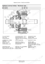
| Brakes and Controls (33) | 526-557 | Parking Brake, Hydraulic Service Brakes |
| Hydraulic Systems (35.000-35.106) | 558-633 | Hydraulic System Technical Data, Pump Control Valves, Variable Displacement Pump, Hydraulic Schemas |
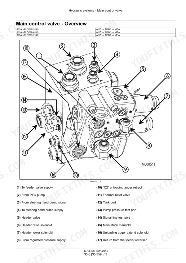
| Auxiliary and Crop Processor Hydraulics (35) | 634-673 | Auxiliary Hydraulic Pump and Lines, Reservoir, Cooler and Filters, Main Control Valve, Header Height System, Crop Processor System |
| Steering and Wheels (41, 44) | 674-723 | Steering Control, Tie Rods, Hydraulic Control Components, Steering Pump, Front Wheels Tighten Procedure |
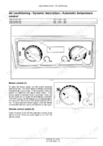
| Cab Climate Control (50) | 724-839 | Heating, Ventilation, Air Conditioning |
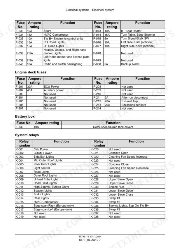
| Electrical System and Engine Electronics (55.000-55.015) | 840-903 | Electrical System Functional Data, Engine Intake and Exhaust Electrical Components |
| Harnesses and Connectors (55.100) | 904-1927 | Harness Component Tables by Circuit, Ground Locations, Wire Connectors and Pin Tables |
| Starting, Instruments, Controls, Precision Farming and SCR Electrical (55.201-55.988) | 1928-2076 | Engine Starting System, Cold Start Aid, Alternator, Battery, Warning Indicators, Alarms and Instruments, A-Post Diagnostic Menu, Feeding Control System, Cab Controls, Ground Speed Control, Electronic Modules, Precision Farming System, Selective Catalytic Reduction (SCR) Electrical System |
| Fault Codes (DTC) | 2077-3292 | Fault Codes for ECU, Ucm, Icm, ATC and A-Post with Context, Cause, Possible Failure Modes and Solution Steps |
| Headers and Product Feeding (58, 60) | 3293-3453 | Attachment/Header Reel Control System, Floating Roll, Feed Chain and Drive, Feeder Housing, Feeder Drive System, Gearbox Housing |
| Threshing (66) | 3454-3569 | Concave, Concave Control System, Threshing Mechanism Drive System, Rotor |
| Separation and Residue Handling (72, 73) | 3570-3637 | Rotary Separator Drive System, Rotary Separator, Straw Chopper Drive System, Straw Chopper, Chaff Spreader |
| Cleaning (74) | 3638-3733 | Cleaning Drive Systems, Upper and Lower Shaker Shoe, Fan Housing, Tailings Return System |
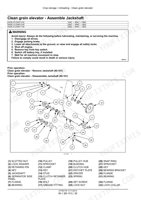
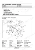
| Crop Storage and Unloading (80) | 3734-3857 | Clean Grain Elevator, Grain Tank, Grain Tank Unload Drive System, Grain Tank Unload |
| Platform, Cab, Bodywork and Decals (90) | 3858-3926 | Engine Hood and Panels, Machine Shields and Guards, Operator Seat, Cab, Cab Interior |
Quick Reference Specifications
| Specification | Value | Page |
|---|---|---|
| Engine model, 6140 and 7140 | Cursor 9, 8.7 l | p. 25 |
| Engine model, 5140 | NEF 6.7, 6.7 l | p. 25 |
| Bore and stroke | Cursor 9: 117 mm / 135 mm; NEF 6.7: 104 mm / 132 mm | p. 25 |
| Compression ratio | Cursor 9: 15.9 to 1; NEF 6.7: 17.0 to 1 | p. 25 |
| Rated power | 5140: 205 kW (275 Hp) with 15 kW (20 Hp) rise; 6140: 260 kW (349 Hp) with 45 kW (60 Hp) rise; 7140: 280 kW (375 Hp) with 50 kW (67 Hp) rise | p. 25 |
| Power boost, unloading | 6140: 25 kW (34 Hp); 7140: 20 kW (27 Hp) | p. 25 |
| Engine idle speed | 600 - 1000 RPM | p. 25 |
| Governor engine speed without load | 2100 RPM | p. 25 |
| Engine oil pressure (warm, rated speed) | 296 - 372 kPa (43 - 54 psi) | p. 25 |
| Engine oil capacity with filter, 6.7 L engine | 18 L (19 US qt) | p. 56 |
| Engine oil capacity with filter, 9L engine | 27 L (29 US qt) | p. 56 |
| Hydrostatic pump capacity at 2100 engine RPM | 332 l/min (87.7 US gpm) | p. 26 |
| Hydrostatic maximum system pressure | 465 bar (6750 psi) | p. 26 |
| Header lift/steering pump capacity at 2100 engine RPM | 166 l/min (43.9 US gpm) minimum (piston pump) | p. 26 |
| Maximum header lift system pressure | 207 bar (3000 psi) | p. 26 |
| Minimum steering relief pressure | 169 bar (2450 psi) | p. 26 |
| Maximum reel drive system pressure | 138 bar (2000 psi) | p. 26 |
| Foot brakes hydraulic pressure | 12.4 bar (180 psi) | p. 26 |
| Rotor diameter and length | 762 mm (30 in) diameter, 2794 mm (110 in) length | p. 26 |
Case IH 5140, 6140, 7140 Common Problems This Manual Covers
DTC 1113: engine coolant temperature sensor voltage higher than expected
The ECU A-9000 is seeing more than 4.93 V on the signal circuit of coolant temperature sensor B-9003. The cause is B-9003 wiring, an internal B-9003 failure, or A-9000 software. Confirm the fault with the EST. Use a multimeter to check the B-9003 circuit for an open, a short and a short to key battery power. Then replace B-9003. If the code comes back, check that the ECU A-9000 has the right software and re-flash it if needed.
Manual Section: Fault codes - DTC 1113 Engine coolant temperature sensor voltage is higher than expected p. 2131E0544-04: ICM 12VD high side supply shorted to low source
The ICM gets switched battery voltage through fuse F-045 at connector X020B pin 2, and it is reading less than 7.0 V. The cause is either wiring or the module. Turn the key switch OFF and disconnect the cab main harness from the ICM at X020B. Check pin 2 for continuity to chassis ground. There should be none. If there is, the short is in the harness between X020B pin 2 and splice point SP-604.
Manual Section: Fault codes - E0544-04 Intermediate Control Module (ICM) high side supply - Shorted to low source p. 2867E0053-03: ladder position sensor shorted to high source
Normal sensor voltage is 0.5 - 3.9 V with the ladder up, 3.9 - 4.9 V with it down and 4.9 - 5.2 V disconnected. Unplug the straw hood harness from ladder position sensor B-247 at X247 and watch the voltage on the display. If it drops back to normal, the short is in the sensor or its wiring, so replace the sensor. If it stays high, disconnect the left main harness from the straw hood harness at X620 and check again.
Manual Section: Fault codes - E0053-03 Ladder position sensor - Shorted to high source p. 2932Slip clutch frozen after the combine sat in storage
A slip clutch can freeze up while the machine sits in the shed between seasons. The manual says it must be burnished before the combine goes back into service. The procedure is Slip clutch - Resurface - Burnish, in section 60.122. Put it on the pre-season list with the rest of the prep work. Do not leave it for the morning you want to start cutting.
Manual Section: Product feeding - Feeder drive system - Slip clutch p. 3354Frequently Asked Questions
What is the front wheel bolt torque on the Axial-Flow 5140, 6140 and 7140?
It is done in two stages. Keep everything dry, with no lube on the bolts or the final drive hub threads. Run each bolt in at least three full turns by hand before any power tool touches it. Follow the ten or fifteen bolt pattern and torque to 200 N·m (148 lb ft). Mark each bolt head against the wheel and turn it another 90°. Next, drive onto a large, firm, level surface and do ten figure 8's. Re-torque every bolt to 1355 N·m (999 lb ft), then do it again after ten hours of operation. p. 717
What is the engine oil capacity with filter on the Case IH Axial-Flow 5140, 6140 and 7140?
The 6.7 L NEF engine in the 5140 takes 18 L (19 US qt) with the filter. The 9L Cursor engine in the 6140 and 7140 takes 27 L (29 US qt) with the filter. Check which engine you have before you open the jugs. p. 56
How do I clear an SCR inducement lock (DTC FBBF)?
DTC FBBF means the inducement system locked after 3 detections in 40 hours. You reset it from the dealer service tool screen Engine Restart Counter Reset. You may also need to run the Engine Restart Counter Reset / Unlock Inducement configuration on the EST. The SCR Fault Repair Verification Test may be needed too, before the machine goes back to work. If it is still locked in final inducement after that, use the Easy Engine software that comes with the EST to clear all faults. None of this lasts unless you find and repair the failure that caused the inducement in the first place. p. 2843
What torque do the Case IH Axial-Flow 5140, 6140 and 7140 front axle final drive bolts take, and how much oil goes in?
Hang the final drive on suitable lifting equipment and fit the alignment bushings, washers and mounting bolts. Torque the bolts at the alignment bushings first, to 508 - 542 N·m (375 - 400 lb ft). Doing those first holds the shafts in line between the transmission and the final drive. Then bring the remaining bolts to the same torque. Fill with 12.3 l (13 US qt) of CASE IH AKCELA GEAR 135 H EP 85W-140. p. 350
When does the rotor impeller flighting blade need replacing on the Case IH Axial-Flow 5140, 6140 and 7140?
Later than most people think. The blade can take a lot of wear before rotor feeding suffers. Replace it if feeding drops off noticeably, if a hook has worn into the blade, or if wear reaches a mounting bolt hole. To measure, hook a tape on the fourth mounting bolt from the front. Draw an arc across the blade face at 330 mm (13 in). If it is worn past that line but still feeds fine, leave it for now. That one check can save you buying a blade you did not need yet. p. 3544





Reviews
There are no reviews yet.