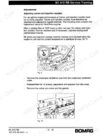
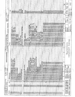
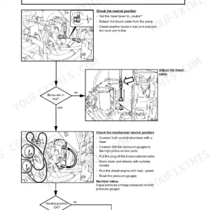
What the DA-control valve on a BC 670 RB actually does when charge pressure drops is settled in this 256-page Bomag BC 670 RB Service Training PDF (OEM 008 098 42), the factory book for the Cummins-powered refuse compactor. Full wiring diagrams walk the electrical system sheet by sheet, from current supply and cold starting aid through the travel control circuit board, with a table of potentials for tracing faults with your meter. Hydraulic schematics map the closed-loop travel circuit, the oil flow amplifier and the dozer blade control, and troubleshooting tables close out the engine, travel and lubrication chapters. Set the charge pressure relief valve at 30 bar, confirm pilot pressure starts pump control at 6 bar, and torque the injection nozzle adjustment screws to 61 Nm. On a landfill cell at night there is nobody to call. Bookmarked and text-searchable, the PDF prints clean; the sheet you need can ride on the machine and take the grease.
Complete the set for your BC 670 RB
Other edition of this manual
What's Inside This Manual
| System | Pages | Key Topics |
|---|
| Service Training | 1 | Bc 670 Rb, Serial Number Identification, Part Number |
| Documentation | 3 | Index of Related Bomag Publications (Each Sold Separately) |
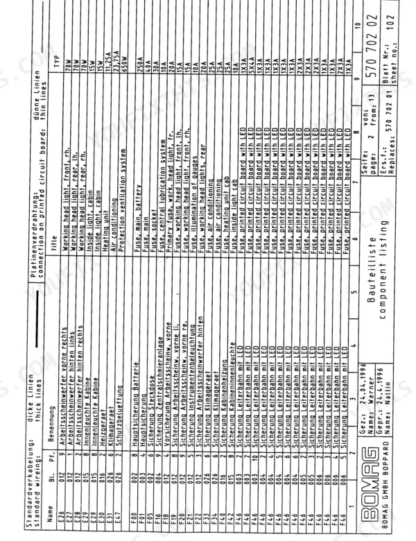
| List of Components | 7 | Component Diagram, Component List, System Identification |
| Technical Specifications | 8-10 | Engine Specifications, Travel Pump Specifications, Travel Motor Specifications, Final Drives Specifications, Steering and Working Pump Specifications, Steering Valve Specifications |
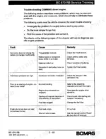
| Diesel Engine | 11-41 | General, External Engine Parts, Turbo Charger, Fuel System, Lubrication Oil System, Coolant System, Air Intake System, Exhaust System |
| Hydraulic System | 42-94 | Travel System |
| Working Hydraulics | 95-114 | Axial Piston Pump, Oil Flow Amplifier, Priority Valve, Control Valve Block, Steering Valve, Dozer Blade Cylinder |
| Electrical System | 115-211 | Bc 670 Rb Electrical System, Checking the Voltage Potentials, Table of Potentials, How to Proceed in Case of an Electrical Fault, Electric Installation Box, Junction Box X41 |
| Lubrication System | 212-240 | Lubrication Pump, Main Distributor, Sub Distributor, Piston Detector, Pump Element, Safety Valve |
| Air Conditioning | 241-256 | Physical Principles, Boiling Point, Refrigerant Circuit, Temperature - Pressure Curve, Refrigerant Circuit Kad 9, Components, Electro Magnetic Clutch, Condenser |
Quick Reference Specifications
| Specification | Value | Page |
|---|
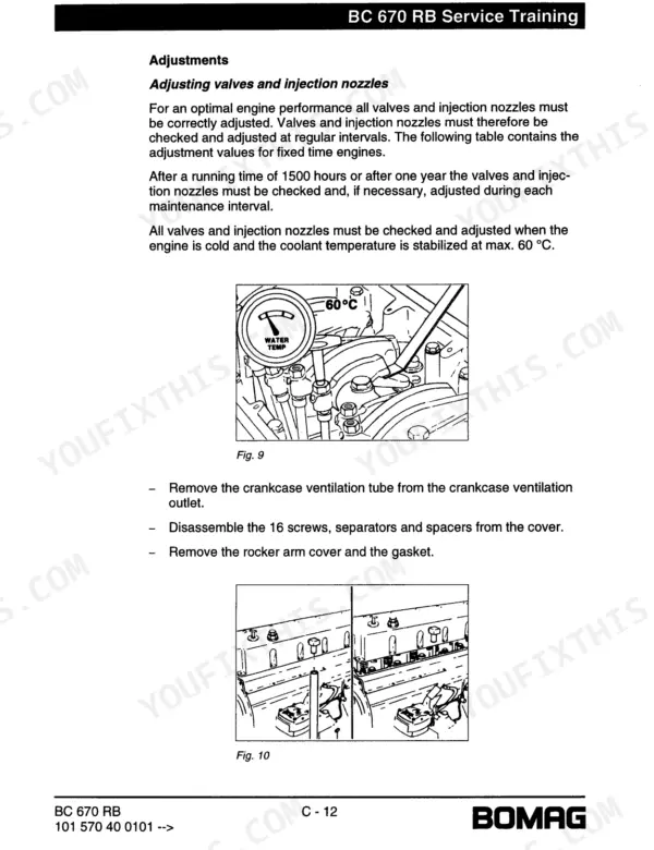
| Injection nozzle adjustment screw tightening torque (without torque wrench adapter) | 61 Nm | p. 33 |
| Injection nozzle adjustment screw tightening torque (with torque wrench adapter) | 47 Nm | p. 33 |
| Charge pressure relief valve setting | 30 bar | p. 52 |
| Pilot pressure at control start | 6 bar | p. 52 |
| Current consumption (Float position) | approx. 1A | p. 112 |
| Current consumption (Down) | approx. 3A | p. 112 |
| Engine Displacement (LTA-10-C325) | 10000 cm3 | p. 8 |
| Engine Displacement (MTA 11 - C 350) | 10800 cm3 | p. 8 |
| Travel Pump Displacement | 71 cm3/U | p. 8 |
| Travel Motor Displacement Range 1 | 70 cm3/U | p. 9 |
| Travel Motor Displacement Range 2 | 200 cm3/U | p. 9 |
| Intake Valve Clearance | 0.36 mm | p. 28 |