
A drum that quits vibrating halfway through a lift is a hydraulic problem, and this 390-page Bomag BW 211 D-3 repair manual PDF (OEM 008 193 60) is the factory route to finding it on your single drum vibratory roller. Troubleshooting diagrams trace the travel, vibration and steering circuits from symptom to failed component, backed by hydraulic schematics and complete flushing procedures for both closed loops. Supplier rebuild sections strip the A4VG and A10VG variable displacement pumps and Series 51 travel motors down to the rotary group, and the drum and oscillating articulated joint each get a full teardown chapter. Set the steering relief at 190 ± 10 bar, then confirm roughly 210 bar in the circuit before closing up. Every hour the roller sits, a lift goes uncompacted. Bookmarked and text-searchable, and detailed enough that you know exactly which piston or valving to order the first time.
Complete the set for your BW 211 D-3
- Repair Manual: Bomag BW 211 D-3 Training Manual — Wiring Diagrams
- Repair Manual: Bomag BW 211 D-3 Service Training — Wiring Diagrams
What's Inside This Bomag BW 211 D-3 Repair Manual
| System | Pages | Key Topics |
|---|---|---|
| General | 5-14 | Foreword, Safety Regulations, General Repair Instructions |
| Tests and Adjustments | 15-36 | Technical Data, Special Tools, Checking the Rotary Speeds, Checking / Adjusting the Neutral Positions of the Travel Pump, Pressure Tests in the Travel Circuit |
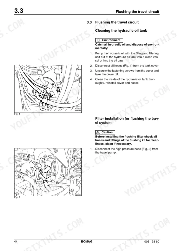
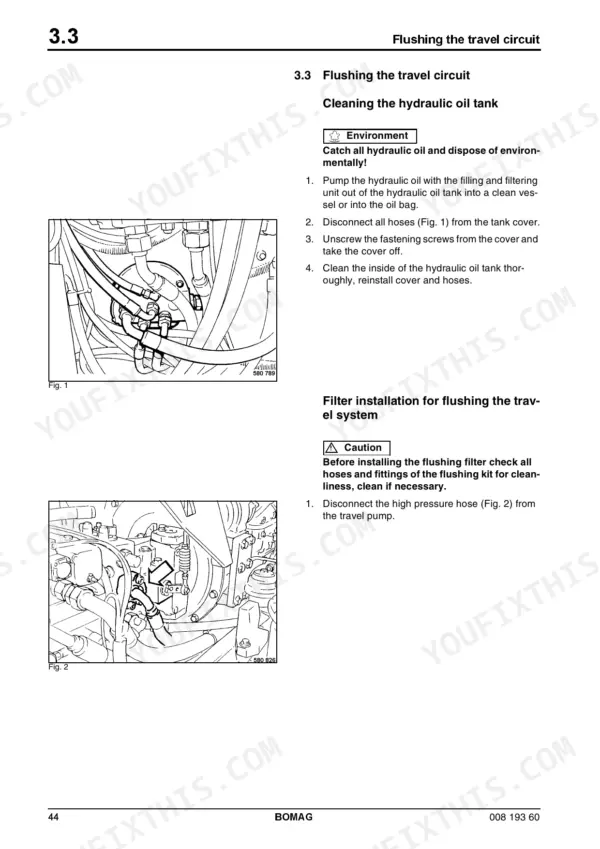
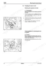
| Flushing | 37-58 | Special Tools for Flushing, Spülschema Fahrantrieb, Flushing the Travel Circuit, Flushing Diagram Vibration Circuit, Flushing the Vibration Circuit |
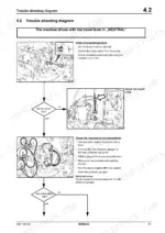
| Trouble Shooting | 59-88 | General Trouble Shooting, Trouble Shooting Diagram |
| Drum | 89-134 | Special Tools, Drum Repair Overview, Removing and Installing the Drum, Repairing the Drum, Disassembling and Assembling the Change-Over Weight, Changing the Rubber Buffers |
| Oscillating Articulated Joint | 135-154 | Special Tools, Oscillating Articulated Joint Repair, Removing and Installing the Oscillating Articulated Joint, Dismantling the Oscillating Articulated Joint |
| Travel Drive Series 51 | 157-238 | Variable Displacement Motors, Loop Flushing Valve, Charge Pressure Relief Valve, Displacement Limiters, Control Systems |
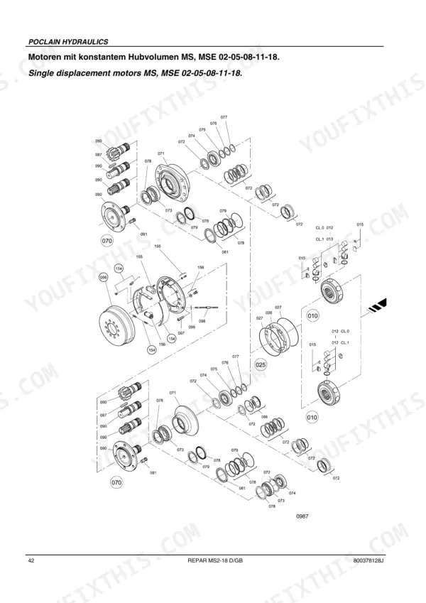
| Ms/Mse 02 to 18 | 239-288 | Hydraulic Motors, Brake Piston, Bearing Support, Brake Shoes, Cam, Cylinders Block Assembly, Valving |
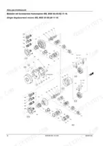
| A4Vg | 289-334 | Variable Displacement Pumps, Drive Shaft, Boost Pump, Control Piston Cover, Control Modules, Rotary Group |
| A10Vg | 335-390 | Variable Displacement Pumps, Drive Shaft, Boost Pump, Control Piston Cover, Control Units, Rotary Group |
Quick Reference Specifications
| Specification | Value | Page |
|---|---|---|
| M4 (8.8) | 3 Nm (2 ft-lb) | p. 11 |
| M4 (10.9) | 5 Nm (4 ft-lb) | p. 11 |
| max. steering pressure | 190 ± 10 bar | p. 18 |
| Steering circuit pressure | approx. 210 bar | p. 35 |
| Steering circuit pressure (pump outlet port) | approx. 200 bar | p. 36 |
| Tightening torque for M 3 bolts (8.8 strength class) | 1.1 Nm | p. 325 |
| Tightening torque for M 4 bolts (8.8 strength class) | 3.1 Nm | p. 325 |
| Operating weight (Cece) | 10620 kg | p. 16 |
| Axle load, drum (Cece) | 6270 kg | p. 16 |
| Axle load, rear (Cece) | 4350 kg | p. 16 |
| Rated speed (Perkins engine) | 2200 rpm | p. 16 |
| Charge pressure limitation | 25 ± 1 bar | p. 17 |
Bomag BW 211 D-3 Common Problems This Manual Covers
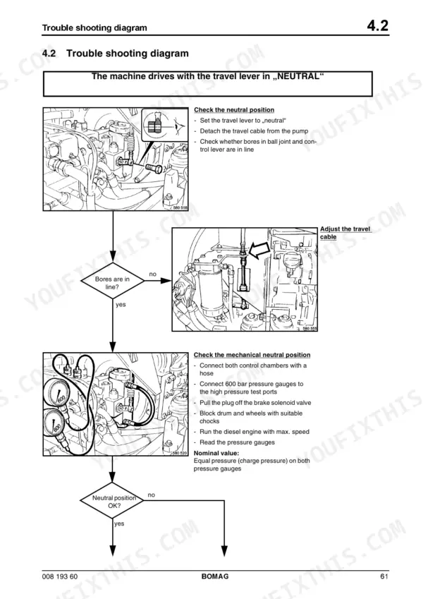
Bomag BW 211 D-3 rolls a few feet then stops, travel drops out in both directions intermittently
Check charge pressure first; the limitation is 25 ± 1 bar, spec on page 17. Verify brake releasing pressure reaches at least 12 bar, then work through the magnetic coil, travel cable, and drum drive motor checks in the Trouble Shooting section starting on page 59. Inspect the coupling between engine and travel pump for sheared elements.
Manual Section: Troubleshooting Diagram: Machine does not drive p. 63Steering wheel very stiff to turn, machine sometimes loses drive at the same time
Test steering pressure at the gauge port; maximum steering pressure is 190 ± 10 bar, listed on page 18. Measure again at the pump outlet port, roughly 200 bar per page 36. Low readings on both point to the steering/charge pump; good pressure with stiff steering means the steering cylinder or a binding articulated joint.
Manual Section: Troubleshooting Diagram: No steering / steering sticky p. 86Machine slowly creeps forward or backward with the travel lever sitting in neutral
Check the mechanical neutral position of the travel lever and cable first, then adjust the hydraulic zero-position of the travel pump using the procedure in Tests and Adjustments, page 15 onward. Verify charge pressure holds 25 ± 1 bar while you adjust, and run the final check at the rated engine speed of 2200 rpm.
Manual Section: Troubleshooting Diagram: Machine drives with travel lever in NEUTRAL p. 61No vibration or vibration comes in weak, drum amplitude feels low on high setting
Verify the magnetic coil on the vibration pump pulls in, then check pilot pressure to the pump. Measure the leak oil rate of the vibration motor; anything over 1.5 l/min, the limit on page 34, means worn motor internals. Confirm frequency reaches 30/36 Hz per page 18; low frequency with good pressure points to vibrator shaft bearings.
Manual Section: Troubleshooting Diagram: No vibration p. 78Drum knocks and bounces during vibration, rubber buffers cracked or torn at the mounts
Inspect every rubber buffer between drum and frame for cracks and separation; replace them as a full set following the Drum section procedure starting on page 89. While the drum is open, check the change-over weight, refill it with 2.5 litres of silicone oil per page 132, and torque the cover screws to 120 Nm, spec on page 133.
Manual Section: Drum p. 89Frequently Asked Questions
What are the torque specifications for screws with metric unified threads on the BOMAG BW 211 D-3?
The tightening torque for metric unified thread screws depends on the screw dimension and strength class. For example, an M10 screw with a strength class of 8.8 requires 50 Nm (37 ft-lb), while an M10 screw with a strength class of 12.9 requires 83 Nm (61 ft-lb). p. 11
What is the nominal charge pressure for the travel circuit on the BOMAG BW 211 D-3?
The nominal charge pressure for the travel circuit is between 24 and 26 bar. This measurement should be taken at an operating temperature of approximately 50 °C. p. 24
What is the nominal leak oil rate for the vibration motor?
The nominal leak oil rate for the vibration motor is a maximum of 1.5 l/min. If the leakage rate exceeds this value, the vibration motor must be replaced. p. 34
What is the nominal high pressure setting for the travel system on the Bomag BW 211 D-3?
The nominal high pressure for the travel system is approximately 483 bar. This is checked by blocking the pressure override valve and actuating the travel lever. p. 27
How much silicone oil is needed when assembling the change-over weight on a Bomag BW 211 D-3?
When assembling the change-over weight, you should fill approximately 2.5 liters of silicone oil 47 V 1000 cst into the basic weight, filling it up to the upper edge of the change-over weight. p. 132
What do I get after purchasing this Bomag BW 211 D-3 manual?
All 390 pages arrive as one searchable PDF at checkout. Read it at the desk, then take the phone out to the machine.
Can I print this Bomag BW 211 D-3 manual?
Yes. Print a chapter or just the pages for the job at hand, for use in your own shop. Any home or office printer works.
Reviews
There are no reviews yet.