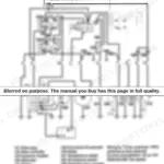
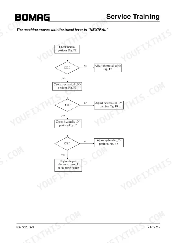

A BW 211 D-3 that quits vibrating mid-lift rarely tells you which relief valve gave up; this 164-page Bomag BW 211 D-3 Service Training PDF (OEM 008 099 75) is the factory training book written to answer that question for the single drum roller. Wiring diagrams trace supply, starting, brake, vibration and speed-range circuits, and the hydraulic schematic maps the closed travel loop from pump to Poclain drum drive motor. Troubleshooting charts walk you from no vibration, or a machine that creeps in neutral, back to a test port and a hard number. Set charge pressure to 25 plus or minus 1 bar at high idle, and confirm the travel pump's high pressure limitation at 475 bar before you condemn a pump. Guess those figures and you cook a hydrostat. Bookmarked, with a working text layer, the PDF rides on whatever screen goes out to the machine with you.
Complete the set for your BW 211 D-3
- Repair Manual: Bomag BW 211 D-3 Repair Manual
Other edition of this manual
What's Inside This Manual
| System | Pages | Key Topics |
|---|---|---|
| Documentation | 3 | Index of Related Bomag Publications (Each Sold Separately) |
| General | 4 | |
| List of Components | 5 | Front Frame, Drum Drive Motor, Articulated Joint, Steering Valve, Operator's Seat, Hydraulic Oil Cooler |
| Test Ports and Connections | 6 | Travel Pump, Vibration Pump, Steering Pump, Brake Control Valve, Drum Drive Motor, Axle Drive Motor |
| Technical Data and Adjustment Values | 7-9 | Engine, Travel Pump, Travel Motor, Drum Drive, Vibration Pump, Steering and Charge Pump |
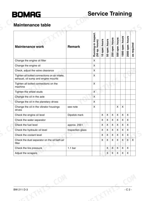
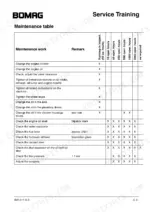
| Maintenance | 10-14 | Maintenance Table |
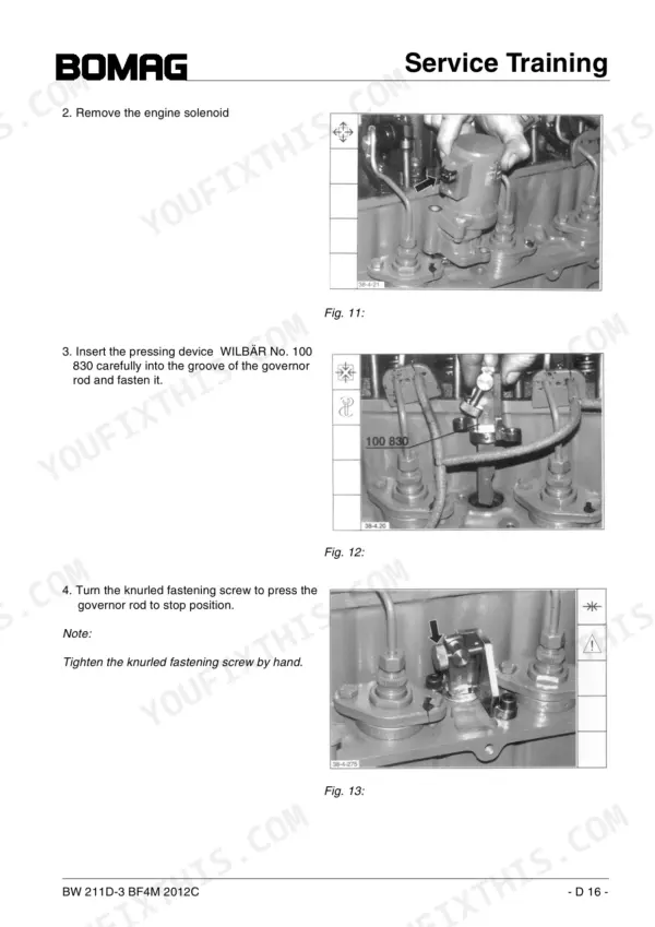
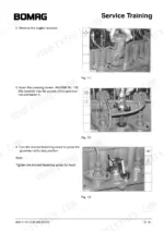
| Deutz Diesel Engine | 15-43 | Service Side, Starter Side, Lubrication Oil Circuit |
| Electrical Components | 44-46 | Heating Flange Module, High Current Relay, Oil Pressure Switch, Engine Solenoid, Pressure Differential Switch, Boost Fuel Valve |
| Travel System | 47-93 | Travel Pump, Control, Charge Pressure Relief Valve, High Pressure Relief Valves, Pressure Override, Drum Drive Motor Poclain Mse 18 2 Cx, Travel Motor, Travel Circuit |
| Vibration System | 94-122 | Vibration Pump, High Pressure Relief Valves, Control, Vibration Motor, Flushing Valve, Drum, Vibration Circuit |
| Steering System | 123-136 | Steering Pump, Steering Valve, Articulated Joint, Steering, Articulated Joint - Assembly Instructions |
| Electric System | 137-147 | Power Supply, Ignition and Starter Circuit, Brakes, Travel Speed Range Selector, Vibration |
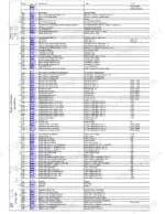
| Electric Schematic | 148-157 | Circuit Diagram, Supply and Starting Unit, Monitoring and Indicators, Heat Flange Control, Brake and Vibration, Back Up Alarm, Speed Ranges, Head Lights, Air Conditioning, Working Head Lights, Omegameter and Terrameter, Printer and Operation Unit |
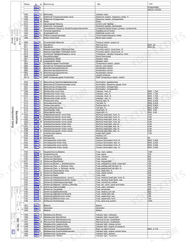
| Component Listing | 158-163 | Relay, Battery, Generator, Indicator Light, Warning Buzzer, Fuse |
| Hydraulic Schematic | 164 | Travel Pump, Charge Pump, Steering Cylinder |
Quick Reference Specifications
| Specification | Value | Page |
|---|---|---|
| High pressure limitation (travel pump) | 475 bar | p. 8 |
| Pressure override (travel pump) | 425+/-15 bar | p. 8 |
| Charge pressure (travel system) | 25 +/- 1 bar | p. 8 |
| Steering pressure relief valve setting | 175 bar | p. 124 |
| Cylinder head cover tightening torque | 9 +/- 1 Nm | p. 42 |
| Crankcase ventilation tightening torque | 9 +/- 1 Nm | p. 42 |
| Injection pump flange screw tightening torque (initial) | 5 Nm | p. 41 |
| Injection pump flange screw tightening torque (final stages) | 7 Nm, 10 Nm and 30 Nm | p. 42 |
| Engine Power (ISO 9249) | 98 kW | p. 8 |
| Valve clearance, inlet | 0.3 mm | p. 8 |
| Valve clearance, outlet | 0.5 mm | p. 8 |
| Engine coolant capacity | 16 l | p. 9 |
| Engine oil capacity | 10 l | p. 9 |
| Hydraulic oil capacity | 60 l | p. 9 |
| Rear axle oil capacity | 11 l | p. 9 |