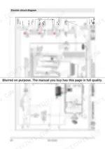
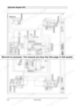
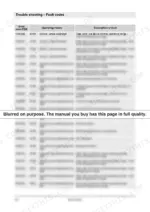
Only the factory source gives the definitive final word on maintaining the Bomag BM 1000/35 cold planer, detailed across this 484-page Service Manual (OEM 008 400 03 EN). Massive electrical and hydraulic schematics map out the travel pump, milling drive, and conveyor belt functions. The troubleshooting charts break down functional conditions for the MTU engine control unit and the axial piston pumps, letting you trace fault codes directly to the source. When adjusting the engine, lock the valve clearance adjustment setscrew nut to exactly 30 Nm, and verify the idler pulley pressures read between 8 and 25 bar before engaging the milling drum. When you are alone on a night shift with a dead machine and no one to ask, having this text-searchable PDF means you own the answers for good. Download the bookmarked file once and keep it on hand for the life of this machine.
What's Inside This Manual
| System | Pages | Key Topics |
|---|
| General Service Training | 7-24 | Introduction - Service Training, Concerning Your Safety (Handling Fuels and Lubricants, Park the Machine in Secured Condition) |
| Technical Data | 25-32 | Dimensions, Weights |
| Total Overview of Machine | 33-52 | Component Overview Electrics, Component Overview Hydraulics |
| Trouble Shooting | 53-198 | Overviews (Overview -: Travel System, Milling Drive, Height Adjustment, Steering, Conveyor Belt Functions, Swivelling the Slewable Chassis) |
| Electric Systems | 199-230 | Control Units, Display (0-Start Screen, 1-Work Screen, 2-Menu, Fault Code Display), Reserve Wiring |
| Engine | 231-270 | Lubrication Oil Circuit, Cooling Circuit, Fuel System, Exhaust Gas Cleaning (Exhaust Gas Recirculation, SCR), Engine Electrics (Control Unit Mtu, Sensors Mtu 6R 1000) |
| Hydraulic System | 271-314 | Component Description, Travel Pump, Conveyor Belt Pump, Fan Pump, Working Pump, Towing the Machine, Trouble Shooting Axial Piston Pumps |
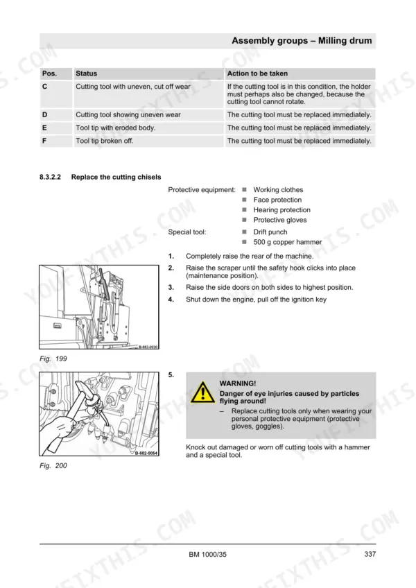
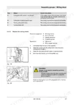
| Assembly Groups | 315-378 | Drive Unit (Description), Milling Unit (Description), Milling Drum (Description, Repair), Conveyor Unit (Description, Undercarriage (Description |
| Appendix | 381-484 | Electric Circuit Diagram, Hydraulic Diagram 293 |
Quick Reference Specifications
| Specification | Value | Page |
|---|
| Hydraulic oil filter element replacement interval | 500 operating hours | p. 21 |
| Tightening torque for valve clearance adjustment setscrew nut | 30 Nm | p. 264 |
| Tightening torque for valve cover screws | 20 Nm | p. 265 |
| Pressures on the idler pulleys (front left, front right, rear left) | 8 - 25 bar | p. 294 |
| Pressures on the idler pulleys (rear right, folded out) | 8 - 25 bar | p. 294 |
| Split scraper floating position orifice | 0.4mm | p. 351 |
| Split scraper imposed load orifice | 2.5mm | p. 301 |
| Fastening screw tensioning torque | 100 Nm | p. 331 |
| Central nut tightening torque | 700 Nm (516 ft·lbf) | p. 343 |
| Engine Oil Capacity | 25 l | p. 23 |
| Fuel Tank Capacity | 590 l | p. 23 |
| AdBlue/DEF Tank Capacity | 95 l | p. 23 |