
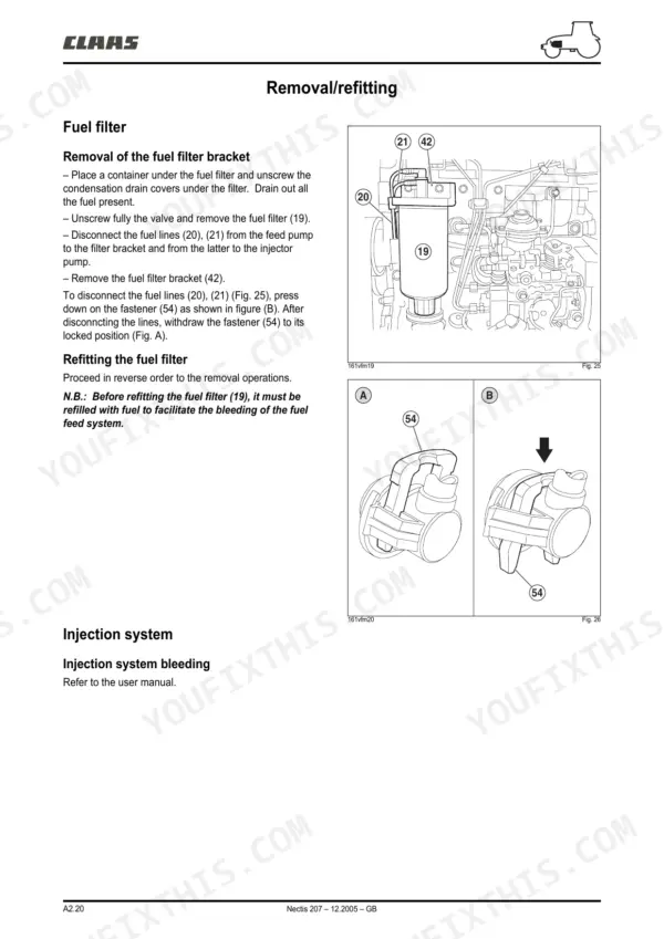
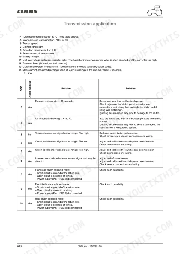
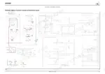

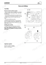
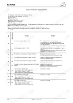
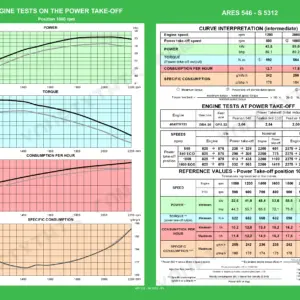
All 861 pages of this Claas Nectis 217, 227, 237, 247, 257, 267, 207 repair manual (OEM #00 11 302 370) exist to put your 2005-2006 tractor back in the field. You get factory wiring diagrams with fusebox layouts, relay charts, and harness connector pinouts, plus hydraulic schematics for the 1-pump, 2-pump, and 3-pump systems. Step-by-step teardowns walk you through the Iveco engine, the T 506 gearbox and rear axle, the suspended front axle, and the TCE 6 electronic linkage. Set camshaft bearing clearance between 0.038 and 0.152 mm, and scrap any valve spring shorter than 63.50 mm unloaded. Chasing a shuttle reverser fault without factory diagrams is a lost afternoon. This bookmarked PDF opens on your phone or tablet; search a spec by keyword, walk out to the tractor, and fix it.
What's Inside This Claas Nectis 207-267 Repair Manual
| System | Pages | Key Topics |
|---|---|---|
| A1 - Test Procedure - Injector Instruction Sheets | 8-17 | Visual Checks, Engine Oil Level, Hydraulic/Transmission Oil Level, Fuel Filters, Turbocharger Pressure, Dynamometer Testing |
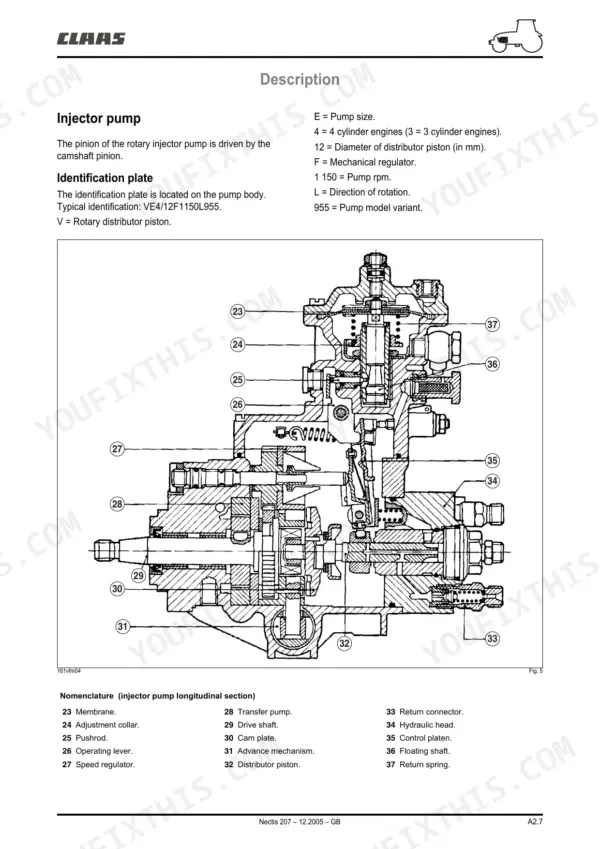
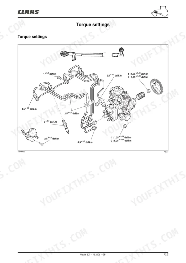
| A2 - Injection Feed | 28-57 | Identification (Injector Pumps), Torque Settings, Description (Injector Pump, Fuel Pump, Line Filter, Fuel Filter, Electrical Components) |
| A3 - Iveco Engine | 62-145 | Lubrication (Operation), Cooling (Operation), Turbocharger (Operation), Dimensions (- Build Clearances, Valves) |
| B1 - Mechanical Part (T 506 Gearbox) | 146-233 | Transmission Kinematics, Dismantling Procedure, PTO and Vehicle Drive Clutch, Mechanical Doubler, Gear Casing |
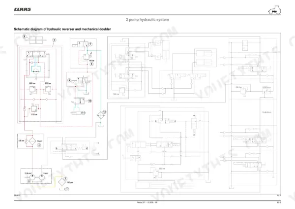
| B2 - Hydraulic Part (T 506 Gearbox) | 234-261 | Pump Hydraulic System, Clutchless Reverser, Lubrication System, Accumulator Pressure |
| B3 - Electronic Components (T 506 Gearbox) | 262-291 | Ehm 24 Electronics Unit, Shuttle Reverser, Clutch Pedal, Electrical Tests, Speed Sensor |
| C1 - Mechanical Part (T 506 Rear Axle) | 292-339 | Drive Pinion, Differential, Axle Tubes, Power Take-Off (PTO), Brakes |
| C2 - Hydraulic Part (T 506 Rear Axle) | 340-357 | Hydraulic System, Differential Lock, Rear Power Take-Off, Braking System, Pressure Checks |
| C3 - Electronic Components (T 506 Rear Axle) | 358-371 | Differential Monitoring, Rear PTO Control, Electrical Tests, Speed Sensor, Differential Lock Switch |
| D1 - Mechanical Part (Front Axle) | 372-465 | Front Axle Loadings, Wheel Alignment, Suspended Front Axle, Steering Actuator, Wheel Hub |
| D2 - Hydraulic Part (Front Axle) | 466-491 | Hydraulic System, Front Axle Engagement, Pressure Checks |
| D3 - Electronic Components (Front Axle) | 492-577 | Electronic Control, Electrical Tests, Engagement Switch, Solenoid Valve |
| E1 - Common Elements (Hydraulics) | 578-625 | Gear Pumps, Steering Unit, Brake Valve, Auxiliary Spool Valves, Linkage System Selector |
| E2 - Pump System 1 (Hydraulics) | 626-655 | Pump Characteristics, Steering Actuator Pressure, Antishock Valves, Auxiliary Spool Valves |
| E3 - 2-Pump System (Hydraulics) | 656-693 | Pump Characteristics, Steering Pump Flow, Dual Spool Valve, Linkage Spool Valve |
| E4 - 3-Pump System (Hydraulics) | 694-719 | Pump Characteristics, Auxiliary Spool Valves, Dual Spool Valve, Linkage Spool Valve |
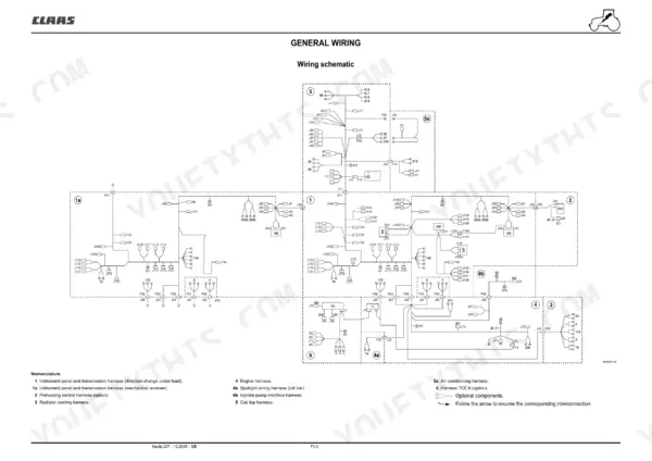
| F1 - Schematic Diagrams (Electrical) | 720-783 | Fusebox, Relays, Starting Circuit, Charging Circuit, Lighting, Instrument Panel |
| F2 - Harness and Connector Paths (Electrical) | 784-819 | Instrument Panel Harness, Engine Harness, Cab Top Harness, Tce 6 Harness, Connector Pinouts |
| G1 - Instrument Panel (Electronics) | 820-843 | Instrument Cluster, Warning Lights, Speed Sensor, Fuel Gauge, Temperature Sensor |
| G2 - Electronic Linkage Tce 6 | 844-861 | Tce 6 Inputs/Outputs, Self-Checking, Position Sensor, Load Sensor, Solenoid Valves |
Quick Reference Specifications
| Specification | Value | Page |
|---|---|---|
| Clearance between bearings and camshaft | 0,038 - 0,152 mm | p. 79 |
| Clearance between bearings and engine block | 0,044 - 0,144 mm | p. 79 |
| Clearance between cam follower and housing | 0,020 - 0,065 mm | p. 79 |
| Spring unloaded: H | 63,50 mm | p. 78 |
| Spring under a load of 32,9 daN (H1) | 49,02 mm | p. 78 |
| Inlet valves clearance | 0.25 ± 0.05 mm | p. 88 |
| Engine Oil Pressure (Hot) | 1.2 to 3.8 bar | p. 65 |
| Coolant Thermostat Opening Temp | 81 ± 2 °C | p. 65 |
| Injector Calibration Pressure | 266 ± 6 bar | p. 29 |
| Engine Compression Pressure | 18 to 22 bar | p. 86 |
| Front Axle Engagement Pressure | 18 bar | p. 451 |
| Brake Valve Pressure | 120 to 150 bar | p. 356 |
Claas Nectis 207-267 Common Problems This Manual Covers
Claas Nectis 217 valve train ticking loudly at idle, clearance won't stay in spec, engine low on power
Remove the valve cover and measure clearances cold. Set inlet valves to 0.25 ± 0.05 mm and exhaust valves to 0.50 ± 0.05 mm per the chart on page 88. If clearance won't hold, measure cam follower to housing clearance against the 0.020 to 0.065 mm limit on page 79, then check camshaft alignment; anything over 0.04 mm means replace the shaft.
Manual Section: A3 - Iveco Engine p. 88Engine cranks but won't start, or fires then dies with white smoke when cold
Check fuel delivery and bleed the filters before blaming injectors. Run a compression test; healthy cylinders read 18 to 22 bar, the figure on page 86. If compression checks out, pull the injectors and pop-test them at 266 ± 6 bar calibration pressure from page 29. Replace any injector that dribbles or opens low.
Manual Section: A3 - Iveco Engine p. 86Engine oil pressure warning light flickers at hot idle after a long day of fieldwork
Verify oil level and grade first, then screw a mechanical gauge into the gallery port. Warm the engine fully; hot pressure should hold between 1.2 and 3.8 bar as listed on page 65. If it reads low, drop the pan and inspect the pump and pickup screen before condemning the bearings.
Manual Section: A3 - Iveco Engine p. 65Four wheel drive won't engage from the cab switch, no clunk from the front axle
Connect a pressure gauge to the front axle engagement circuit and cycle the switch with the engine running. You need 18 bar to close the clutch, the figure on page 451. If pressure is low or absent, test the solenoid valve coil and its wiring before splitting anything mechanical.
Manual Section: Front Axle Engagement Diagnostics p. 451Brake pedal feels soft and tractor pulls to one side under hard braking
Bleed both brake circuits, then tee a gauge into the brake valve outlet and stand on the pedal. Confirm 120 to 150 bar per page 356. If pressure is good but the pull remains, expect worn discs on one side; pull the trumpet housing and inspect. Equalize both pedals before road use.
Manual Section: C2 - Hydraulic Part (T 506 Rear Axle) p. 356Frequently Asked Questions
What are the torque specifications for the CLAAS Nectis 227 engine/transmission link?
The engine/transmission link requires 8 daN.m plus Frenetanch (242) for the 4 screws (HM12x125-65) and 8 daN.m plus Frenetanch (242) for the 8 screws (HM12x175-50). p. 82
What are the replacement specifications for the camshaft bearings?
The camshaft bearings (47) must be pressed into their respective housings. The internal diameter of the front and rear bearings (47) and intermediate bearings (48) must be measured along two axes perpendicular to one another, with the bearing internal diameter being 54,083 to 54,147 mm. p. 99
What is the specified valve clearance for the engine?
For a cold engine, the inlet valve clearance is 0,25 ± 0,05 mm and the exhaust valve clearance is 0,50 ± 0,05 mm. p. 88
What is the required engine oil pressure for the Iveco engine?
The engine oil pressure should be between 0,7 and 3,5 bar when the engine is warmed up. p. 86
What is the compression pressure range for the engine cylinders?
The compression pressure for the engine cylinders should be between 18 and 22 bar. p. 86
How will I receive this Claas Nectis 217 & variants Repair Manual?
Immediate download of the complete 861-page searchable Repair Manual. Access it on any device, from a laptop at your desk to a phone in the field.
Can I print this Claas Nectis 217 & variants manual?
Yes. The PDF has no DRM restrictions, so print any page or section you need for your shop. Works with any standard printer.
Reviews
There are no reviews yet.