
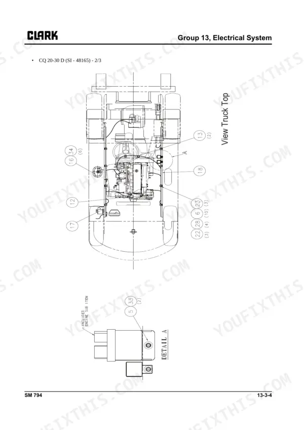
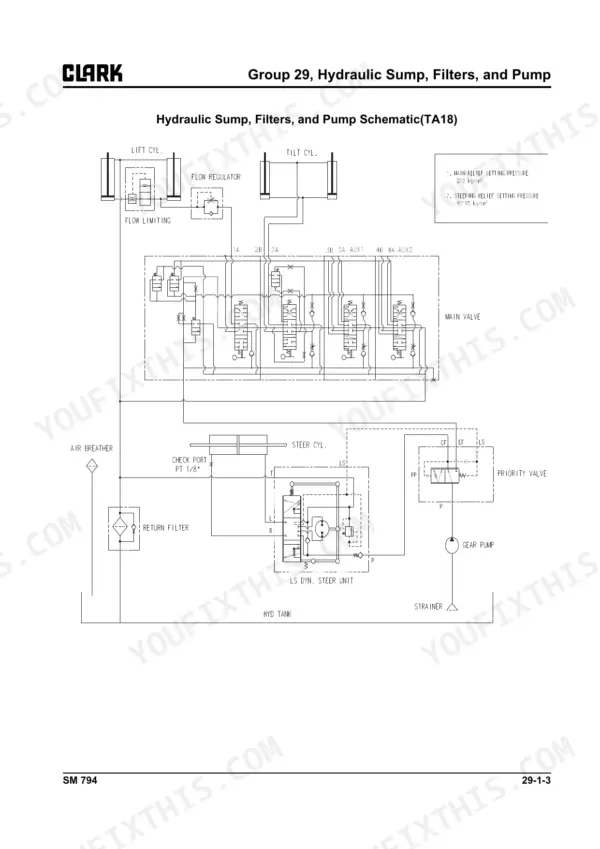
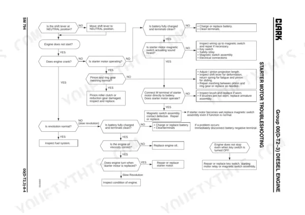
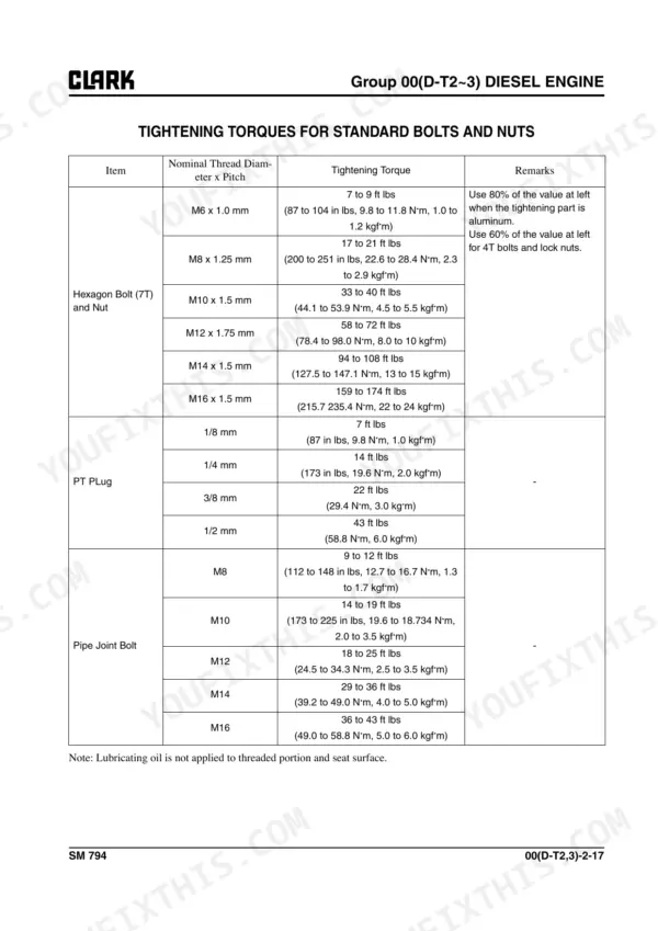
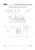
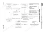
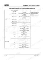
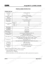
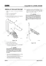
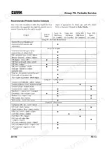
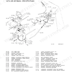
Pull the upright section open on a Monday morning and you are checking carriage roller clearance with the shim tables right in front of you, because this 729-page Clark CQ20, CQ25, CQ30 service manual pdf (D/L variants included) covers the whole forklift family across seventeen factory chapters. Electrical circuit diagrams map the instrument pod and parts arrangement wire by wire, and the lift circuit chapter runs its hydraulic schematic straight into pressure checks and control valve adjustment. Troubleshooting tables carry real weight here, running through fuel, ignition, brake, steering, and upright faults until each one ends at a repair. On the diesel engine the thermostat should crack at 160 F (71 C) and stand fully open by 185 F (85 C); the water outlet bolt pulls to 14 N-m (10.1 lbf-ft). Every hour that truck sits idle is an hour of freight nobody moved. Bookmarked, text-searchable, and yours to keep wherever the machine happens to be parked.
What's Inside This Clark CQ20, CQ25, CQ30 Manual
| System | Pages | Key Topics |
|---|---|---|
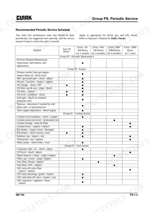
| Periodic Service | 4-19 | Maintenance Schedules, The Planned Maintenance Program |
| Engines | 20-290 | Safety, General Service Information, Periodic Maintenance, Engine |
| Cooling System | 291-308 | Specifications and Description, Engine Cooling System Testing and Maintenance, Radiator Removal and Replacement |
| Fuel System | 309-444 | Fuel System Specifications and Description, Fuel System Troubleshooting, Fuel System Adjustments and Maintenance |
| Air Induction System | 445-456 | Specifications and Description, Air Induction System Troubleshooting, Air Induction System Service |
| Transaxle | 457-490 | Structure and Maintenance, Disassembly, Assembly |
| Ignition System | 491-522 | Ignition System Description and Specifications, Ignition System Troubleshooting, Ignition System Inspection, Adjustments, And Timing, Distributor Overhaul |
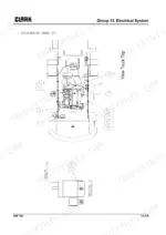
| Electrical System | 523-570 | Cautions for Working on the Electrical System, Specifications and Features of Electrical System, Electrical Circuit Diagram and Electrical Parts Arrangement, Instrument Pod |
| Wheels and Tires | 571-584 | Wheels and Tires Specifications and Description, Pneumatic Wheels and Tires |
| Brake / Inching System | 585-597 | Braking/Inching System Specifications and Description, Service Brake Troubleshooting, Brake/Inching Pedals and Linkages Adjustments, Brake Bleeding, Brake Master Cylinder Service |
| Steering Column and Gear | 598-604 | Outline, Troubleshooting Table, Priority Valve Disassembly and Assembly |
| Steer Axle | 605-619 | Steering Axle Specifications and Description, Steer Axle Removal and Replacement, Steer Axle Overhaul, Steer Cylinder Removal and Replacement, Steer Cylinder Overhaul |
| Hydraulic Pump, Sump, and Filters | 620-636 | Hydraulic Sump, Filters, And Pump Specifications and Description, Hydraulic Pump and Troubleshooting, Hydraulic Filters and Fluid Maintenance |
| Hydraulic Control Valve/Lift Circuit | 637-652 | Hydraulic Control Valve/Lift Circuit Specifications and Description, Hydraulic System Schematic, Hydraulic System Troubleshooting, Hydraulic System Pressure Checks and Adjustment |
| Tilt Cylinders | 653-664 | Tilt Cylinder Specifications and Description, Tilt Checks and Adjustments, Tilt Cylinder Removal and Replacement, Tilt Cylinder Overhaul |
| Upright | 665-716 | Upright Specifications and Description, Troubleshooting, Upright Inspection, Carriage and Upright Roller Clearance Checks and Shim Adjustments, Cylinder Removal, Shimming, Overhaul |
| Counterweight, Sheet Metal & Chassis | 717-729 | Counterweight Specifications and Description, Counterweight Removal and Replacement, Overhead Guard/Operator’s Cell Removal and Replacement, Floorboard, Radiator Cover |
Quick Reference Specifications
| Specification | Value | Page |
|---|---|---|
| All Models | ||
| Thermostat opening temperature | Starts to open at 160°F (71°C), fully opens at 185°F (85°C) | p. 165 |
| Starter Motor Nominal Output | 3.0 HP (2.3 kW) | p. 180 |
| Starter Motor No-load Terminal Voltage / Current | 11 V / 140 A max | p. 180 |
| Water outlet bolt torque | 1.4 kgf·m (10.1 lbf·ft) [14 N·m] | p. 251 |
| Thermostat Open (cracking) temperature | 82°C ± 1.5° (180°F ± 2.7°) | p. 292 |
| Wheel mounting lug nuts torque | 637~718 Nm (471~531 lbf·ft) | p. 464 |
| Adaptor plate to converter housing and converter housing to transmission housing attaching screws torque | 30~33 Nm (22~25 lbf·ft) | p. 489 |
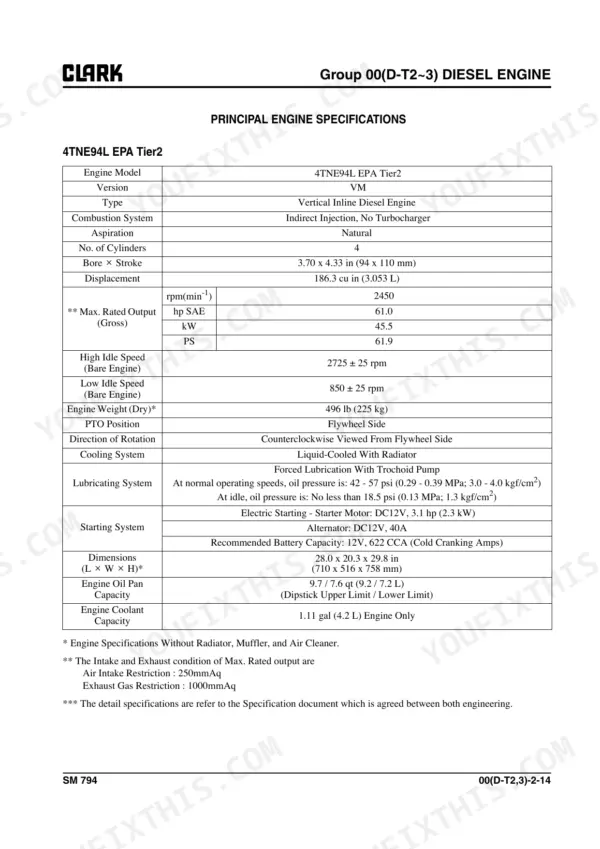
| Engine Oil Capacity (4TNE94L/4TNE98) | 9.2 / 7.2 L | p. 40 |
| Engine Oil Capacity (4G64 LPG/Gas) | 4.0 L | p. 224 |
| Engine Coolant Capacity (4TNE94L/4TNE98) | 4.2 L | p. 43 |
| CQ 20-30 L | ||
| Tightening torque | 4.1~5.1 kg.m | p. 546 |
| CQ20-30 | ||
| Drive Wheel Mounting Nut Torque (1 Piece black) | 640-720 N⋅m (470-530 ft⋅lb) | p. 572 |
Clark CQ20, CQ25, CQ30 Common Problems This Manual Covers
Clark CQ20 temperature gauge climbing into the red zone during normal lift cycles, coolant steaming at the cap
Pull the thermostat and drop it in hot water with a thermometer. It should crack open at 82°C ± 1.5° (180°F ± 2.7°) per the specs on page 292 and run fully open by 95°C. Replace any unit that sticks. Refill and bleed to the 4.2 L coolant capacity listed on page 43.
Manual Section: Cooling System p. 292Engine cranks over but will not fire, or spins slowly and drags on a cold morning
Load test the battery first, then bench test the starter. Check no-load draw against the 11 V / 140 A maximum and 4100 rpm minimum on page 193. Measure brush height and pull anything under the 0.354 in (9 mm) wear limit. Set pinion projection to 0.012 to 0.059 in (0.3 to 1.5 mm).
Manual Section: Electrical System p. 193Steady coolant drip and white crust around the water outlet elbow at the cylinder head
Drain below the outlet, remove the elbow, and scrape both faces clean down to bare metal. Never reuse the old gasket. Torque the water outlet bolts evenly to 14 N·m (10.1 lbf·ft) per page 251, working in a cross pattern. Refill, run to operating temperature, and recheck the joint dry.
Manual Section: Cooling System p. 251Forks lift slow or jerky under load, and the mast drifts down when parked
Warm the hydraulic fluid, then tee a gauge into the lift circuit and stall the cylinder. Main relief should hold 20500 to 21500 kPa as listed on page 638. Low or wandering pressure means a worn pump or a leaking relief. Check control valve tie bolts at 38 to 43 N·m (28 to 32 ft·lb).
Manual Section: Hydraulic Control Valve/Lift Circuit p. 638Transmission slips under load, engagement delayed shifting into forward or reverse, converter running hot
Check transaxle fluid level and condition at operating temperature before tearing anything down. Burnt fluid means clutch pack wear. Inspect the selector valve detent for a broken spring or worn ball. On reassembly, torque the control valve assembly bolts to 16 to 22 Nm (12 to 16 lbf·ft) per page 489.
Manual Section: Transaxle p. 489Steering goes heavy at low speed and the wheel requires constant correction to hold a straight line
Verify hydraulic fluid level and bleed air from the steer circuit first. Install a gauge and check relief pressure against the 8620 to 9300 kPa setting on page 606. If pressure is low, inspect the priority valve before condemning the steer gear. Confirm steer axle linkage and stops are tight and free of slop.
Manual Section: Steer Axle p. 606Frequently Asked Questions
What are the torque specifications for the Clark CQ20-30 drive wheel mounting nuts?
For pneumatic tires on CQ20-30 models, the 1-piece black lug nuts should be torqued to 640-720 N⋅m (470-530 ft⋅lb). If the truck is equipped with 2-piece yellow zinc dichromate lug nuts, the crisscrossing torque sequence should be 300-370 N⋅m (225-275 ft⋅lb). p. 572
What are the thermostat replacement specs for the 4G64 LPG/Gas engine in a Clark CQ20 CQ25 CQ30 forklift?
The thermostat for the 4G64 LPG/Gas engine has a valve opening temperature of 82°C (180°F) and is fully open at 95°C (203°F). p. 248
What engine oil viscosity is recommended for the 4G64 LPG/Gas engine in a Clark CQ20 CQ25 CQ30 forklift?
For the 4G64 LPG/Gas engine, it is recommended to use 10W30 oil that is API class SJ or higher. p. 231
What is the correct cylinder head bolt torque for the 4G64 LPG/Gas engine in a Clark CQ20/CQ25/CQ30 forklift?
The cylinder head bolts on the 4G64 LPG/Gas engine should be tightened to 2.0 kgf·m (14.5 lbf·ft) [20 N·m] plus a 1/4 turn (90°) and then another 1/4 turn (90°). Before final tightening, they must be tightened to 8.0 kgf·m (57.9 lbf·ft) [78 N·m] and then completely loosened. p. 251
What is the recommended service interval for changing the hydraulic fluid on the CQ20-30?
The hydraulic fluid should be changed every 2000 hours of operation or as necessary. p. 632
How quickly can I access this Clark CQ20 manual after buying?
You get a 729-page searchable PDF that downloads instantly after checkout. Open it on your laptop, tablet, or phone, and bring it right to the shop floor.
Is this Clark CQ20 Service Manual printable?
Yes. The PDF is DRM-free, so printing works from any reader and any printer.


Reviews
There are no reviews yet.