
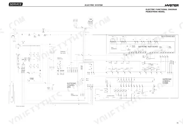
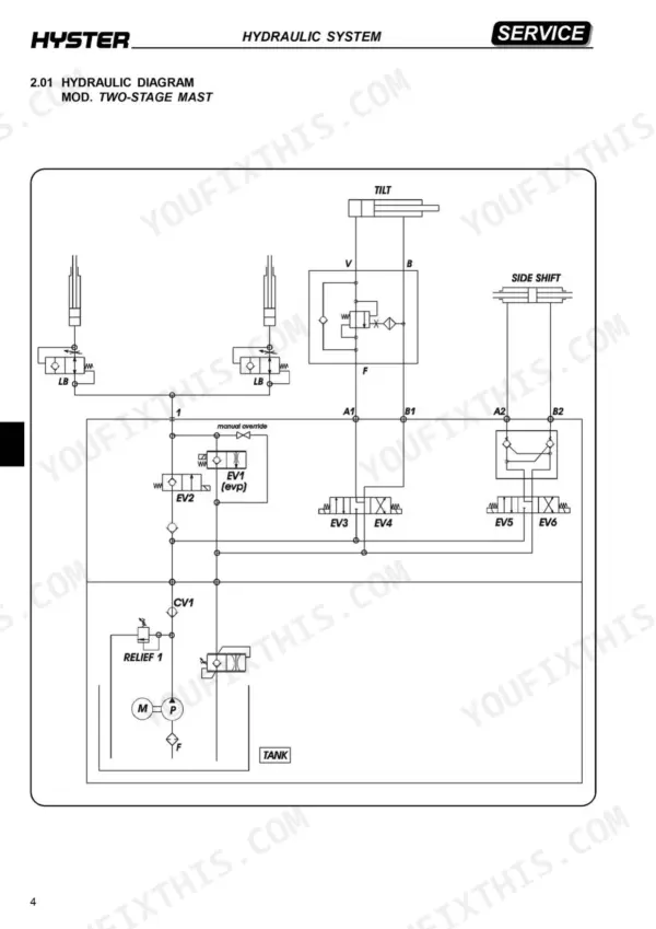
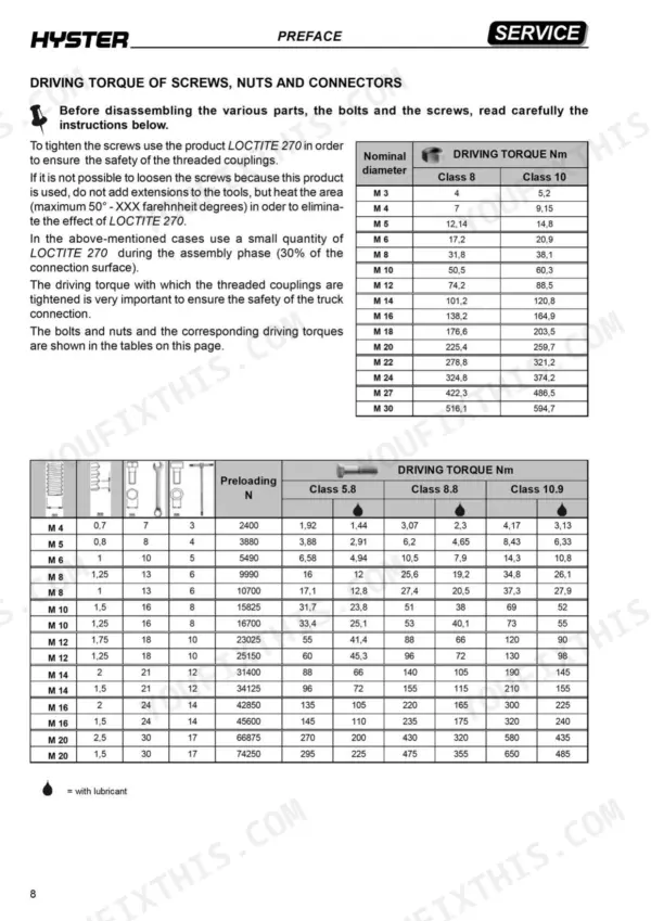
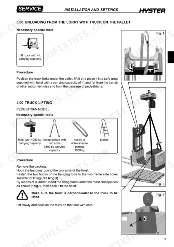
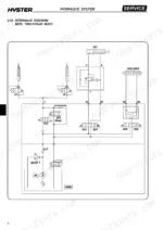
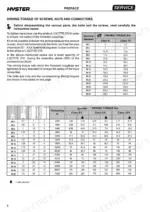
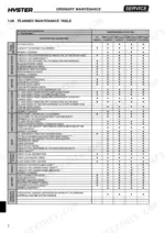
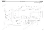
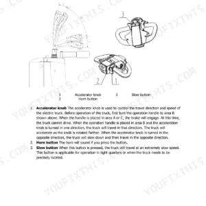
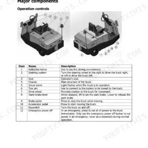
Written for the Hyster S1.0C, S1.2C and S1.5C in pedestrian and swing over tiller configurations, this 271-page factory book (OEM ID 1626965) also shows where the truck and mast serial numbers are stamped, so you can confirm the fit. As a Hyster S1.0C service manual PDF, it pairs wiring diagrams and a connector key to symbols with hydraulic schematics tracing the power pack functions. Diagnostic alarms are grouped by source: the Combi controller, the EPAS controller and the tiller controller. Fit a 10 A fuse at FU3. Torque M16 Class 8 screws to 138.2 Nm, or 164.9 Nm for Class 10. For routine service, the Planned Maintenance Table sets out your scheduled checks, with a lubricant table alongside. Bookmarks and a text layer take you straight to the mast chain, reduction gear or brake pages, and the fuse swap and screw torques get done to the book's own figures.
What's Inside This Hyster S1.0C, S1.2C, S1.5C Manual
| System | Pages | Key Topics |
|---|---|---|
| Introduction | 13-22 | Presentation of the Various Models, Identification Data and Residual Capacity (Plate Positioning, Stamping of the Truck and Mast Serial Number), Configuration of Pedestrian Models |
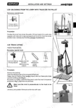
| Installation and Settings | 23-30 | Truck Assembly, Truck Lifting, Battery Installation |
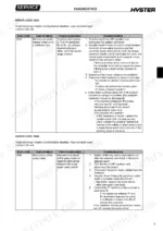
| Diagnostic | 31-58 | Alarms Derived From Combi Controller, Alarms Derived From Epas Controller, Alarms Derived From Tiller Controller |
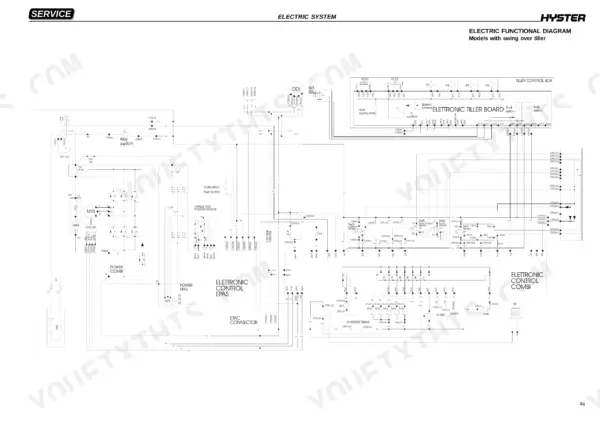
| Electric System | 59-133 | Wiring Diagrams, Connector Connection Key to Symbols, Electrical Components |
| Hydraulic System | 134-187 | Hydraulic Functions of the Trucks, Hydraulic System Symbols, Hydraulic Power Pack Component Table |
| Frame Mechanics | 188-219 | Drive Wheel, Load Wheels, Steering Tiller |
| Mast Mechanics | 220-247 | Mast Features, Chains, Two Stage Mast Mod Beta |
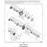
| Reduction Gear | 248-259 | Reduction Gear Components, Removal of the Reduction Gear |
| Braking System | 260-265 | Drive Motor Electromagnetic Brake Components, Braking Systems |
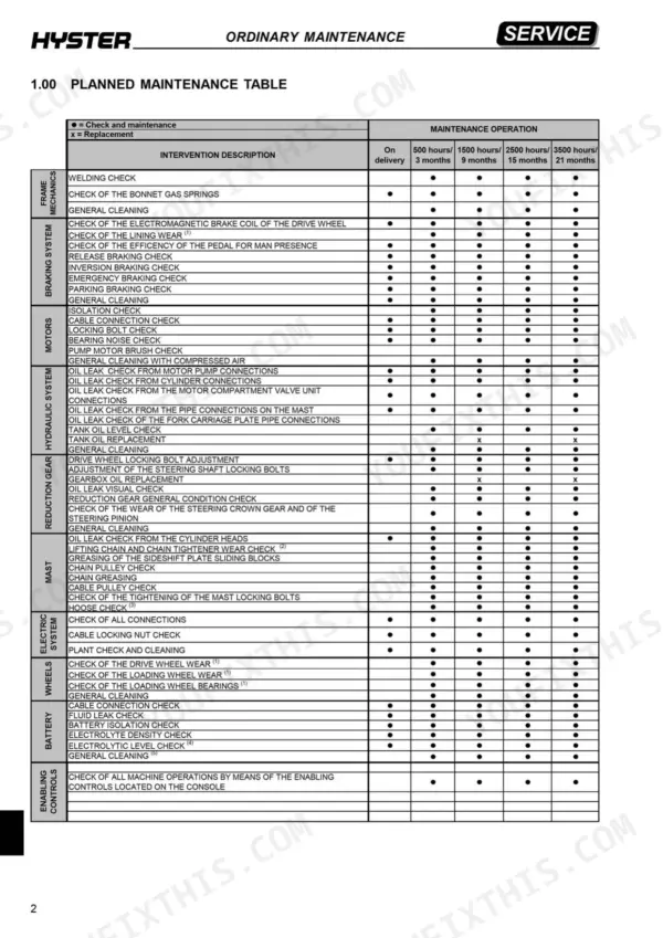
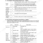
| Ordinary Maintenance | 266-271 | Planned Maintenance Table, Lubricant Table, Cleaning Products |
Quick Reference Specifications
| Specification | Value | Page |
|---|---|---|
| Driving torque for M4 screws (Class 8) | 7 Nm | p. 8 |
| Driving torque for M14 screws (Class 8) | 101.2 Nm | p. 8 |
| Oil flow rate | 20 - 30 liters | p. 159 |
| Main contactor voltage drop | higher than 2V | p. 49 |
| FU3 fuse rating | 10 A | p. 9 |
| Pump body capacity | 3.2 cc | p. 140 |
| Electromagnetic brake coil resistance (short-circuit to B+ check) | lower than 15Ω | p. 51 |
| Electromagnetic brake lining clearance | not over 0.35 mm | p. 264 |
| MTR AC drive motor power | 4.5 kW | p. 195 |
| M8 check nuts of the supply cables | 12 Nm | p. 207 |
| Drive wheel fastening screw torque | 200 Nm | p. 192 |
| Sensor for enabling mast | under 500 mm | p. 87 |
Hyster S1.0C, S1.2C, S1.5C Common Problems This Manual Covers
Hyster S1.0C S1.2C S1.5C error 12832 battery low voltage, traction and hydraulics disabled with red DDI LED
Measure battery voltage between the controller B+ and B- terminals following page 36 and confirm it matches the nameplate; the controller trips below 16V. Check voltage drop across the main contactor and controller fuse, replacing either above 0.5V at full system current. Disconnect the battery before tightening B+ terminal screws, as page 4 bans maintenance with it connected. Recharge the battery, then check its real capacity.
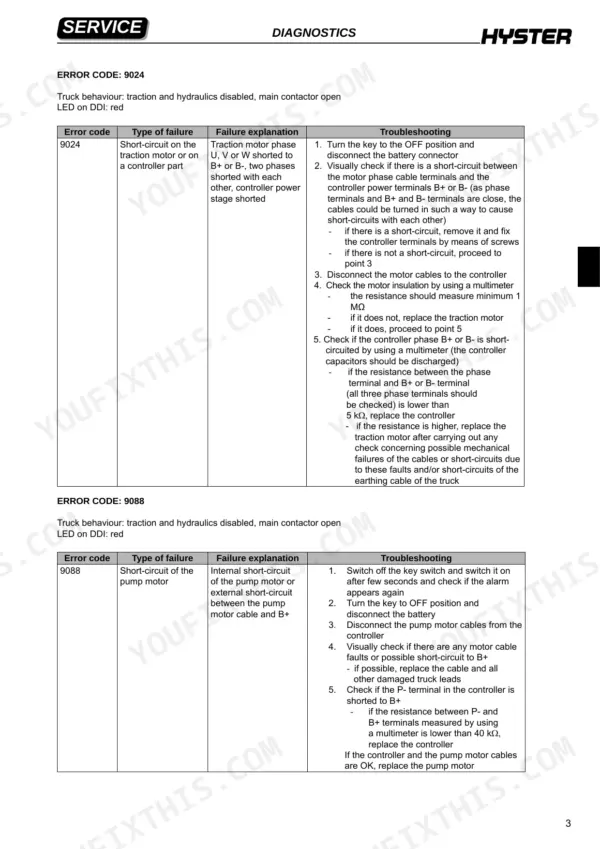
Manual Section: Alarms Derived From Combi Controller p. 36Error 9088 pump motor short-circuit, traction and hydraulics disabled with main contactor open
Check whether 9088 returns after cycling the key switch, per page 33. Turn the key OFF, disconnect the battery, and wait at least 90 seconds before removing any power cable unless an external resistance discharges the capacitors (page 113). Disconnect the pump motor cables and inspect them for shorts to B+. Measure P- to B+: below 40 kΩ, replace the controller. If controller and cables are good, replace the pump motor.
Manual Section: Alarms Derived From Combi Controller p. 33Error 9090 pump overcurrent alarm with traction enabled and hydraulics disabled on red DDI
Check the PumpMaxCurr parameter following page 35, reset it to default and adjust maximum pressure to the correct value. Verify the pump motor is not mechanically blocked and the lifting mechanism has no binding. Confirm the load does not exceed nameplate lift capacity. Replace the maximum pressure valve if it misbehaves, the pump motor if blocked, or else the controller.
Manual Section: Alarms Derived From Combi Controller p. 35Error 16912 controller power stage overtemperature above 85°C with traction and hydraulics disabled
Check air temperature inside the truck following page 36; above 45°C, increase motor compartment cooling. Compare the controller base plate and cooling ribs: over 5°C difference, check for silicone grease between them and a secure controller mount. Reduce use, then cycle the key after 5 minutes. If the code returns with the base plate under 60°C, replace the controller.
Manual Section: Alarms Derived From Combi Controller p. 36Error 17168 traction motor overtemperature above 155°C, traction disabled while hydraulics still work
Check air temperature inside the truck per page 38; above 45°C, increase motor compartment cooling. Turn the key OFF and disconnect the battery, as page 4 requires for maintenance. Measure the motor temperature sensor connector: above 1450 Ohms with stack temperature below 130°C, replace the sensor. Check for overload or a partially blocked motor. If the code returns after 10 minutes with the motor below 130°C, replace the controller.
Manual Section: Alarms Derived From Combi Controller p. 38Error 9024 traction motor phase short-circuit, traction and hydraulics disabled with main contactor open
Turn the key OFF and disconnect the battery connector following page 33, then check for shorts between motor phase terminals and controller B+ or B- terminals. Wait at least 90 seconds before removing any power cable unless an external resistance discharges the capacitors (page 113). Disconnect the motor cables and test insulation: below 1 MΩ, replace the traction motor. If controller phase to B+ or B- reads under 5 kΩ, replace the controller.
Manual Section: Alarms Derived From Combi Controller p. 33Frequently Asked Questions
What do Hyster S1.0C/S1.2C/S1.5C error codes mean?
Error codes are displayed on the DDI with a numerical code preceded by two letters identifying the module in alarm. For example, 'Co' indicates a 'COMBI' controller alarm, 'Ep' indicates an 'EPAS' steering motor control alarm, 'Ti' indicates a 'TILLER' box board alarm, and 'Dd' indicates a 'DDI' display control alarm. p. 32
Why won’t my Hyster S1.0C/S1.2C/S1.5C lift or drive?
If the truck is not lifting or driving, check the DDI for an error code. For example, error code 9024 indicates a short-circuit on the traction motor or controller, which disables both traction and hydraulics. You must turn the key to OFF, disconnect the battery, and follow the specific troubleshooting steps for that code on page 33. p. 33
What are the replacement specs for the 24 V traction battery on the Hyster S1.0C, S1.2C, S1.5C forklift?
The battery capacity for the S1.0C is 24/300 V/Ah with a weight of 260 kg, while the S1.2C and S1.5C models use a 24/400 V/Ah battery weighing 330 kg. Before assembling the battery on the truck, it must be recharged using a suitable charger. p. 19
What torque should I use on the hydraulic power pack tank screws on a Hyster S1.0C, S1.2C, S1.5C forklift?
The four screws fastening the tank to the flange on the 3KW hydraulic power pack must be tightened to a driving torque of 4 Nm. p. 207
How do I adjust the maximum pressure valve on the hydraulic system?
To adjust the maximum pressure valve, unloose the valve lock nut with a 10 mm socket wrench. Use a 4 mm Allen wrench to unscrew the screw until lifting is enabled by the pump, then tighten the screw until the cylinders move upward, and finally tighten the valve by one fifth of a turn. Ensure the outside diameter of the socket wrench is not higher than 13.5 mm. p. 151
What do I get after purchasing this Hyster S1.0C manual?
A 271-page Service Manual in searchable PDF format, available the moment you complete checkout. View on computer, tablet, or phone, with no shipping wait.
Is this Hyster S1.0C Service Manual printable?
Yes. Print a single page or a chapter for your own shop use, on letter or A4.


Reviews
There are no reviews yet.