| Frame and Connected Parts | 1-4 | Introduction (General, Description) |
| Engine Removal and Installation | 5-10 | Engine Mounts, Transmission, Hydraulic Lines, Throttle Cable, Fuel Line, Exhaust Pipe |
| Cab | 14-16 | Cab Frame, Window Replacement, Windshield Wipers, Heater, Heater Hoses |
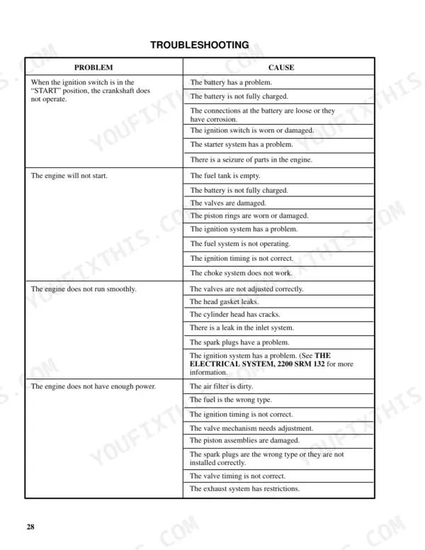
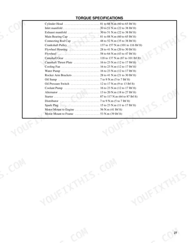
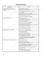
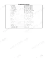
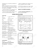
| Mazda M4-121G Engine | 17-47 | Checks and Adjustments (Valves, Throttle Linkage), Engine Specifications (Torque Specifications), Troubleshooting |
| Isuzu C240 Diesel Engine | 48-91 | Fuel System, Timing Gear Case, Camshaft, Crankshaft and Main Bearings, Flywheel and Ring Gear, Pistons and Connecting Rods, Cylinder Block and Cylinder Liners |
| LPG Fuel System | 92-129 | Repairs (Lpg Tank, Replace the Hoses, Hydrostatic Relief Valve, Filter Unit, Vaporizer, Carburetor, Carbureter) |
| Transmission | 130-161 | Introduction (General), Repairs (Control Valve) |
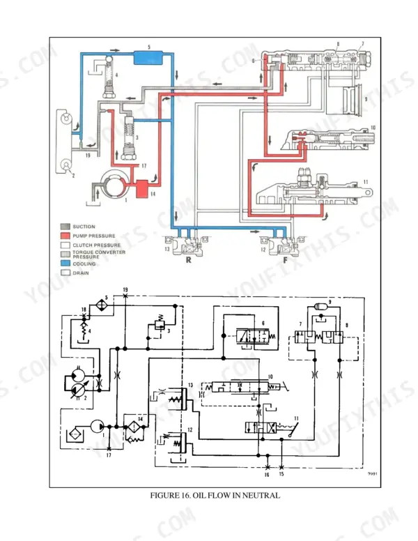
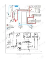
| Single Speed Powershift Transmission | 162-180 | Introduction (General), Description and Operation (General, Torqe Converter, Clutch Assemblies, Hydraulic System, Control Valve, Differential, Oil Flow Diagrams) |
| Single Speed Powershift Transmission (T41-43) | 181-249 | Description and Operation, Clutch Assemblies, Control Valve, Monotrol Pedal, Troubleshooting |
| Drive Axle | 250-254 | Introduction (General, Description), Repairs (Removal, Cleaning, Inspection, Assembly), Troubleshooting, Specifications |
| Steering Axle | 255-262 | Introduction (Description, General), Repairs (Steering Axle, Removal, Installation, Steering Cylinder, Service, Hubs, Spindles) |
| Steering Control Unit | 263-309 | Introduction (General, Description, Operation), Repairs (Steering Wheel and Column Assembly, Type "a" Steering Column Assembly, Type "a" Steering Column, Type "B" Steering Column) |
| Brake System | 310-342 | Introduction (General, Description and Operation), Repairs (Removal and Disassembly, Cleaning and Inspection, Assembly and Installation) |
| Lift Cylinders | 343-354 | Removal, Tilt Cylinders with O-Ring or Single Lip Seals |
| Electrical System (Isuzu C240) | 355-400 | Starting System, Charging System, Starter, Ballast Resistor Relay, Alternator |
| Electrical Warning Devices | 401-404 | Horns, Warning Lights, Buzzers, Bells, Horn Relay, Flashing Units |
| Safety Procedures When Working Near the Mast | 405-407 | Safety Chains, Mast Weldments, Carriage, Lift Cylinders, Free-Lift Cylinders |
| Vista Masts | 448-468 | Description, Carriage, Vista Three-Stage Masts |
| Three-Stage Masts | 469-571 | Removal, Disassembly, Cleaning and Inspection, Assembly, Installation, Lift and Tilt Cylinders, Side Shift Carriage, Sequence Valve |
| Electrical Meters | 572-584 | Description, Replacement, Sender Replacement |
| Main Control Valve | 585-599 | Introduction (General, Description, Operation, Solenoid Valve for Auxiliary Function), Repairs (Main Control Valve |