Hyster S40XL, S50XL, S60XL, S2.00XL, S2.50XL, S3.00XL Service Manual

$39.99 USD · one-time payment

Model: S40XL | S50XL | S60XL | S2.00XL | S2.50XL | S3.00XL
Type: Lift Truck
Serial: A187 | B187 | C187
710 Pages·36 MB·Searchable PDF·English·Print-Ready
  • ✓ Wiring Diagrams
  • ✓ Hydraulic Schematics
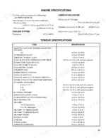
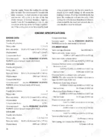
  • ✓ Torque Specs
  • ✓ Multi-Level Bookmarks (3-level navigation)
Preview Sample Pages (PDF)
Add to Cart
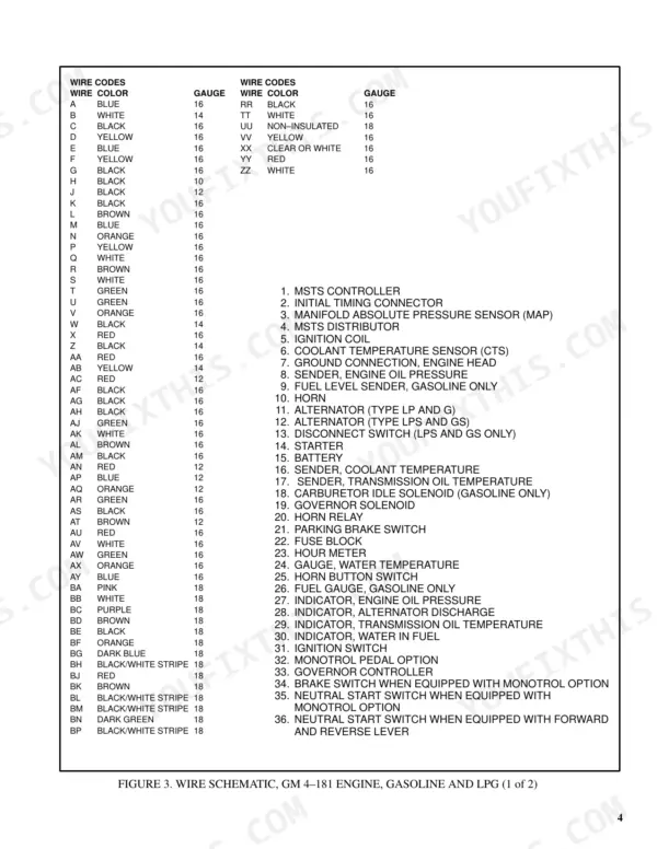
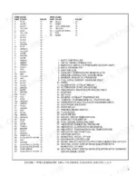
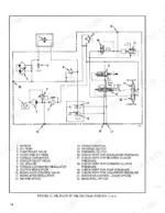
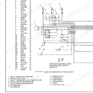
Hyster S40XL, S50XL, S60XL, S2.00XL, S2.50XL, S3.00XL wiring diagram wire color codes and component index for GM 4-181 engine.
Hyster S40XL, S50XL, S60XL, S2.00XL, S2.50XL, S3.00XL Service Manual
$39.99

Instant Download 24/7

  • Works on PC, Mac, tablet, and phone.
  • Download once, keep forever


Guaranteed Safe Checkout
Visa Mastercard PayPal Apple Pay Google Pay

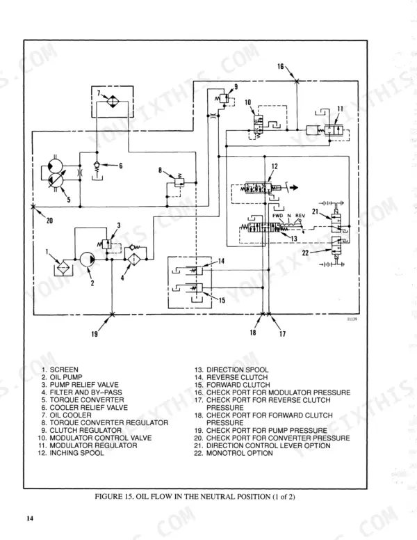
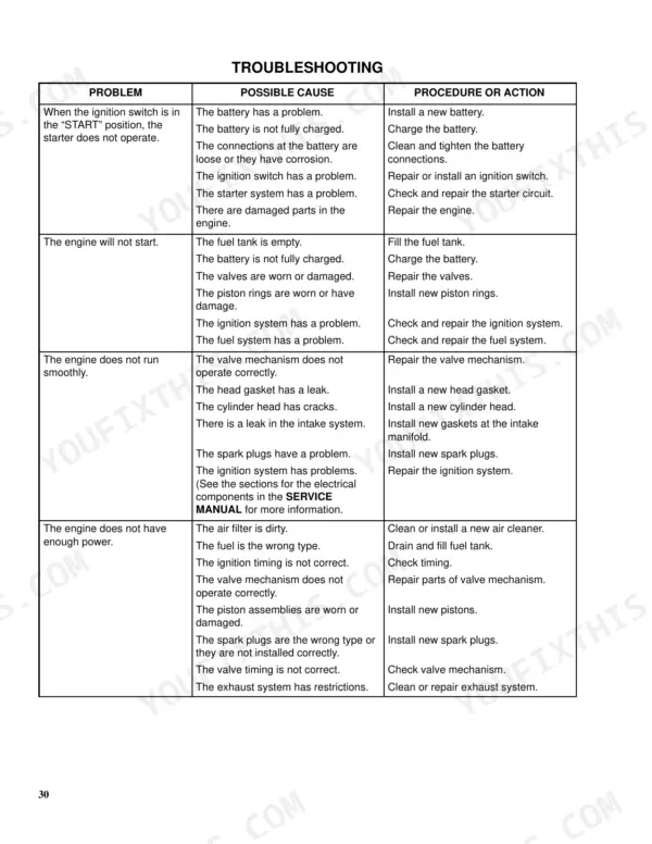
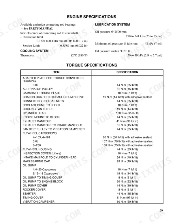
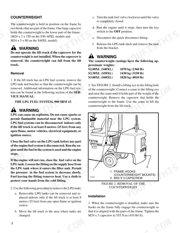
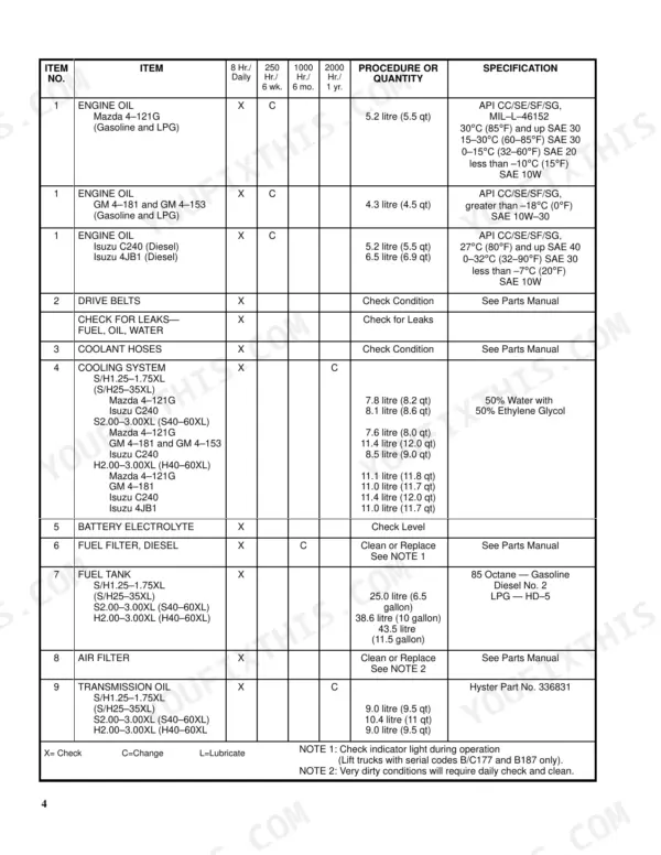
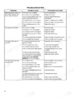
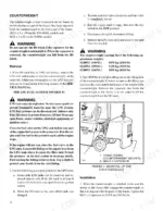
Counterweight removal is the first repair in this 710-page Hyster S60XL service manual PDF (OEM ID 910461), written for six XL lift truck variants running from the S40XL through the metric S3.00XL designation. Wire schematics for the GM 4-181, Mazda M4-121G and Isuzu diesel engines sit with the hydraulic system and transmission schematics, so you can trace a charging circuit or a pump line back to its source. Troubleshooting sections cover the single-speed powershift transmission, the 260 mm and 310 mm service brakes, the steering control unit and the Vista masts with side-shift carriage. Radiator caps are rated at 103 kPa (15 psi), and counterweight capscrews take 555 N.m (410 lbf ft). If you are working through the 250-hour list, lift chains, fork wear and mast lubrication are all set out, with valve clearance due at 1000 hours and powershift transmission service at 2000. Bookmarked and searchable, your download goes wherever the truck does.

What's Inside This Manual

SystemPagesKey Topics
Frame1-14Introduction (General, Description)
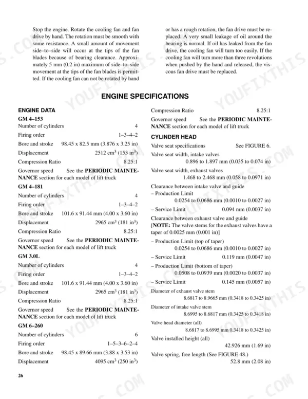
GM Engines15-45Introduction (General, Removal and Installation of the Engine)
Mazda M4-121G Engine46-76Checks and Adjustments (Valves, Throttle Linkage), Engine Specifications (Torque Specifications), Troubleshooting
Isuzu C240 Diesel Engine77-180Cylinder Head, Crankshaft and Main Bearings, Lubrication System, Cooling System, Checks and Adjustments
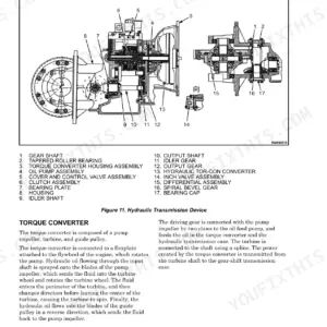
Single-Speed Powershift Transmission181-260Description and Operation, Control Valve
Drive Axle261-265Introduction (General, Description), Repairs (Removal, Cleaning, Inspection, Assembly), Troubleshooting, Specifications
Steering Control Unit266-292Description, Assembly
Steering Axle293-299Introduction (General, Description), Repairs (Steering Axle Assembly, Wheels, Spindles, Bearings, And Tie Rods, Steering Cylinder), Troubleshooting, Torque Specifications
Steering System300-310The Steering System, Description, Operation, Steering Wheel and Column Assembly, Steering Control Unit, Checks and Adjustments
Service Brakes and Parking Brake311-343Description and Operation, Removal and Disassembly of the 260 Mm Service Brakes, Cleaning, Inspection, Assembly and Installation of the 260 Mm Service Brakes
Hydraulic System344-354Gear Pump, Flow Control Valve, Relief Valve, Lift Cylinder, Tilt Cylinder, Main Control Valve
Chain Drive Assembly355-359Introduction (General, Description), Repairs (Removal and Disassembly, Cleaning, Inspection, Assembly and Installation), Troubleshooting (General)
Main Control Valve360-391Introduction (General, Operation, Solenoid Valve for Auxiliary Function), Repairs (Main Control Valve
Alternator with Regulator392-413General, Alternator Repair, Low Output Check, High Output Check, Brushes Circuit Check (Delco Alternators, Motorola Alternators), Diodes Check
Starter414-451General, Description and Operation, Starter Repair (Remove, Disassemble, Clean, Assemble, Install), Troubleshooting
Electrical System (Isuzu C240)452-499Starting System, Charging System, Alternator, Starter, Glow Plugs, Battery
Microprocessor Spark Timing System500-535Pulse Generator, HEI Module, Manifold Absolute Pressure Sensor, Coolant Temperature Sensor, Electronic Control Module, Initial Timing Connector
Lift Cylinders536-569Safety Procedures When Working Near Mast, General, Description (Lowering Control Valve, Cylinders)
Vista Masts570-710Introduction (General, Mast Weldments, Carriage, Mast Mounts), Vista® Two-Stage Mast (Description and Operation), Vista® Free-Lift Mast (Description, Operation)

Quick Reference Specifications

SpecificationValuePage
All Models
LPG tank distance from open flame or ignition source8 metres (25 feet)p. 2
Counterweight capscrew torque555 N.m (410 lbf ft)p. 2
Cylinder head bolt torque88 N.m (65 lbf ft)p. 72
Radiator cap pressure rating103 kPa (15 psi)p. 118
LPG fuel tank pressure1.7 MPa (240 psi)p. 144
Steering wheel nut torque40 to 54 N.m (30 to 40 lbf ft)p. 308
Relief valve adjusting screw jam nut torque28 to 31 N.m (20 to 23 lbf ft)p. 309
Steering relief pressure for H40-60XL10.6 to 11.4 MPa (1550 to 1650 psi)p. 353
S50-60XL
Counterweight Capscrew Torque (M24 x 3 x 150)555 N.m (410 lbf ft)p. 2
S40XL
Counterweight Capscrew Torque (M24 x 3 x 80)555 N.m (410 lbf ft)p. 2
GM 4-153, GM 4-181
Cylinder Head Bolt Torque (GM 4-153/4-181)130 N.m (95 lbf ft)p. 43
S2.00–3.00XL (S40–60XL)
Steering relief pressure for S2.00–3.00XL (S40–60XL)9.9 to 10.7 MPa (1450 to 1550 psi)p. 309
BrandHyster
ModelS40XL, S50XL, S60XL, S2.00XL, S2.50XL, S3.00XL
Machine TypeLift Truck
Manual TypeService Manual
LanguageEnglish
FormatSearchable PDF (Digital Download)
Pages710
File Size36 MB
Manual No.910461
Serial RangeA187, B187, C187
Wiring DiagramsYes
Hydraulic SchematicsYes
Torque SpecificationsYes
Bookmarked / IndexedYes