
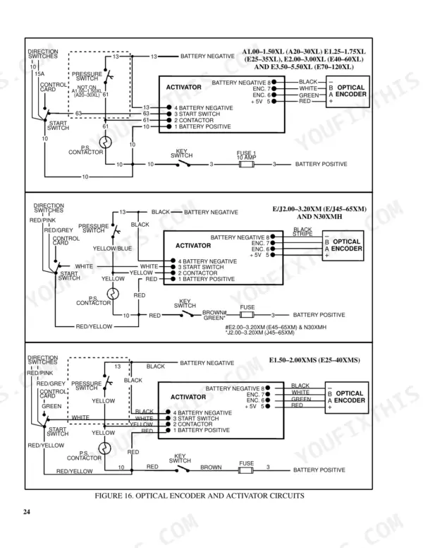
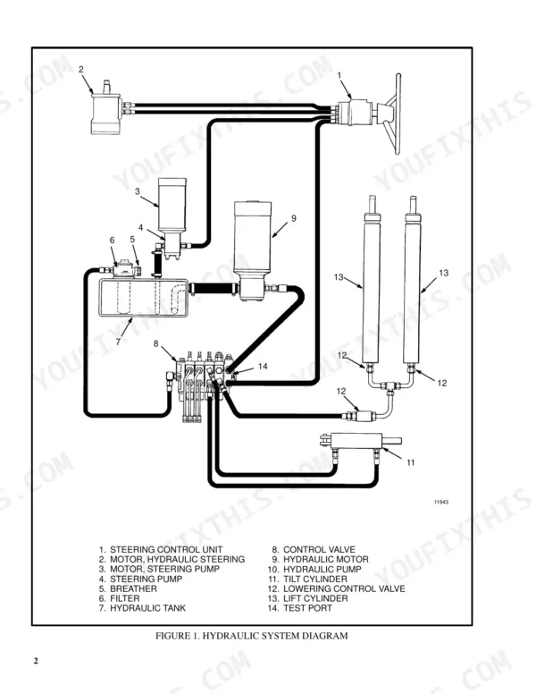
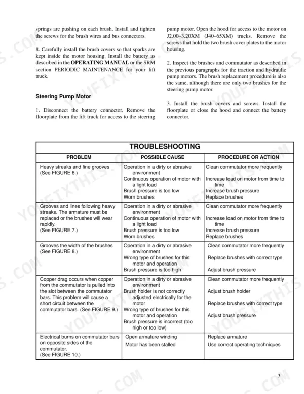
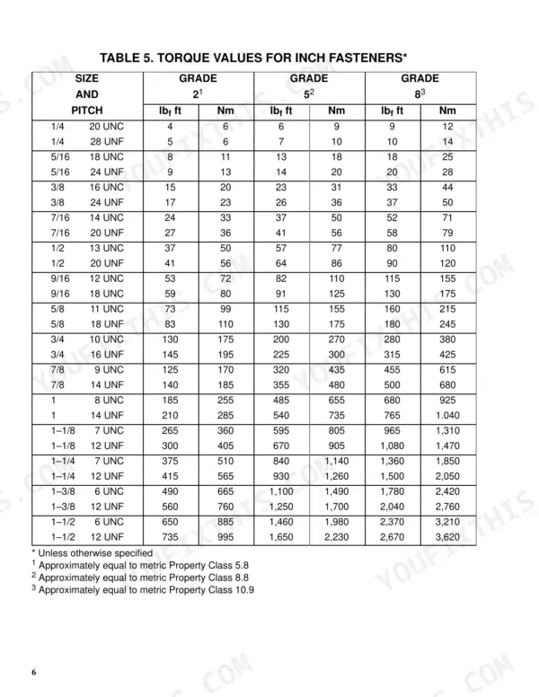
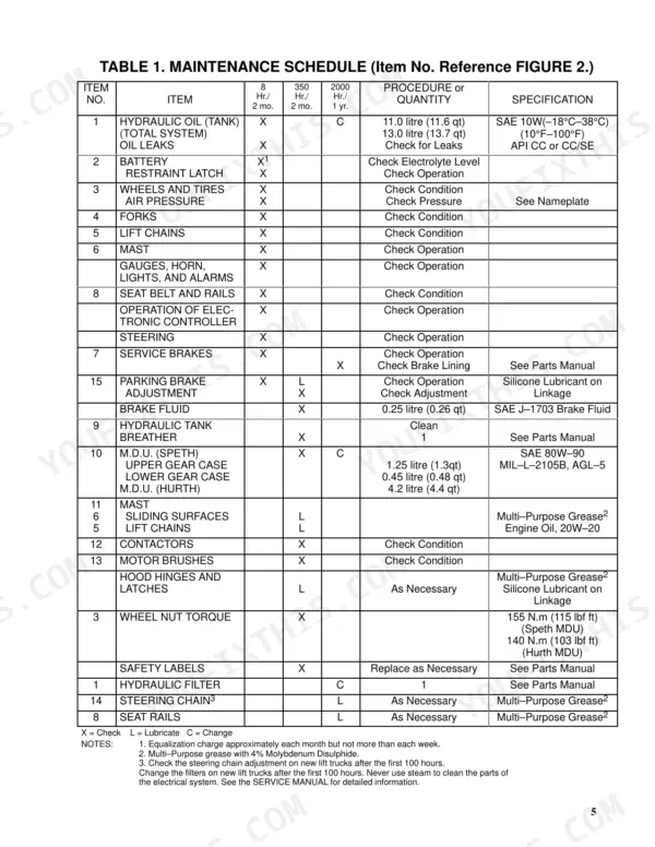
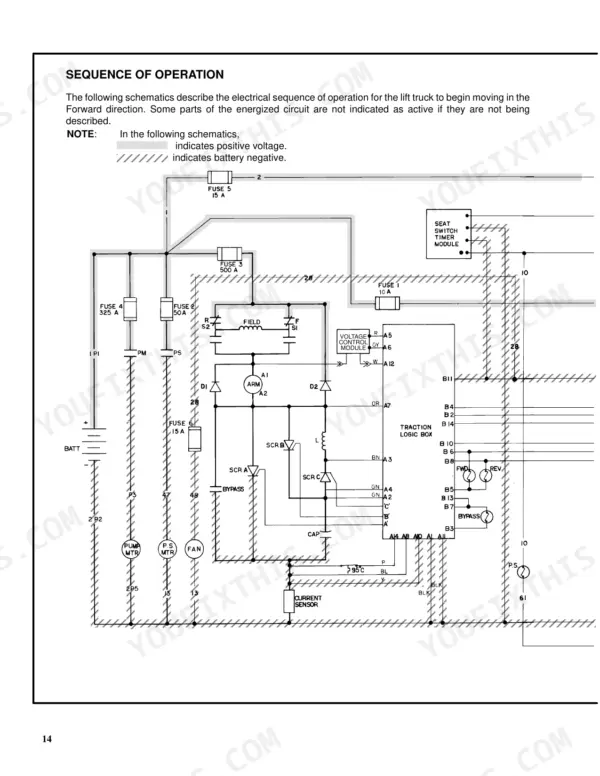
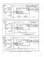
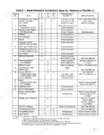
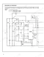
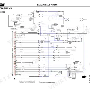
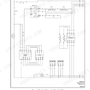
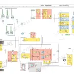
Replacing traction motor brushes, adjusting MDU backlash and bleeding air from the brake system are each laid out in this 386-page Hyster service manual (OEM 897065), which covers the A1.00XL, A1.25XL and A1.50XL lift trucks (A20XL, A25XL, A30XL). Wiring diagrams and hydraulic schematics anchor this Hyster A1.00XL service manual PDF, joined by Sevcon MC400G troubleshooting organised by fault number and a logic box pin arrangement table. Service intervals run from every 8 hours to 350 and 2000 hours. Fastener tables list torque values for inch and metric hardware. Replace any brush worn to 3 mm (0.060 in), and bring counterweight-to-frame capscrews to 320 N.m (236 lbf ft). Perhaps your truck will not move in either direction because the direction contactors close and then immediately open; that fault has its own diagnostic sequence here. Bookmarked and text-searchable, the file travels with you to wherever the truck is parked.
What's Inside This Hyster A1.00XL–A1.50XL (A20XL–A30XL) Manual
| System | Pages | Key Topics |
|---|---|---|
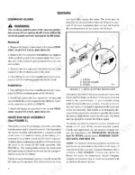
| Parts of the Frame | 1-7 | Introduction (General, Description), Repairs (Overhead Guard, Hood and Seat Assembly, Counterweight, Hydraulic Tank, Safety Labels), Battery Specifications |
| Magnetism | 9-11 | Magnetism and Permanent Magnets, Electromagnetic Fields, Electromagnets, Electromagnetic Induction, Magnetic Force on a Conductor |
| Basic Motors | 12-33 | Motor Operation, Commutation Principle, Direction of Motor Rotation, Motor Speed, Motor Torque, Counter Electromotive Force, Typical Motor, Types of Motors |
| Motor Maintenance | 34-50 | Brush Inspection, Commutator Surface, Brush Replacement, Stoning Procedure, Bearing Lubrication, Motor Disassembly |
| Master Drive Unit | 51-80 | Introduction (General), Repairs (Removal, Disassembly, Assembly, Installation) |
| Steering Control Unit | 81-99 | Introduction (General, Description, Operation), Repairs (Steering Wheel and Column Assembly, Type "a" Steering Column Assembly, Type "a" Steering Column, Type "B" Steering Column) |
| Power Steering Motor and Pump | 100-103 | Description, Removal and Disassembly, E1.25-3.00Xl, J2.00-3.00Xl, E2.00-3.20Xm, N30Xmh, E3.50-5.50Xl |
| Hydraulic Steering Motor | 104-134 | Description, Repairs |
| Brake System | 135-146 | Introduction (General, Description and Operation), Repairs (Master Cylinder, Early Models, Master Cylinder, Late Models, Service and Parking Brakes) |
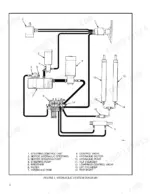
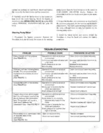
| Hydraulic System | 147-194 | Introduction (General, Description), Control Valve (Description, Operation, Repairs, Checks and Adjustments), Hydraulic Pump (Description, Repairs), Troubleshooting, Specifications |
| Electrical Warning Devices | 195-198 | Operator Controlled Horns, System Warning Lights, Buzzers, Bells, Reverse Warning Horns, Flashing Units |
| Sevcon Motor Controller | 199-251 | Logic Box, Contactors, Thermal Protection, Current Limit, Accelerator Potentiometer, Plugging Circuit |
| Battery Maintenance | 252-265 | Safety Procedures, Maintenace Records, New Battery, How to Clean the Battery, How to Add Water, Hydrometer, Battery Temperature, Charging the Battery |
| Battery Indicators | 266-280 | Introduction (General, Indicators with Meter Movements, Battery Indicators with LCD or LED Displays) |
| Mast Safety Procedures | 281-283 | Removal From the Lift Truck, Disassembly, Cleaning and Inspection, Assembly, Installation |
| Lift Cylinders | 284-306 | Description, Lowering Control Valve, Removal of the Lift Cylinders Without Removing the Mast, Disassembly, Assembly, Installation of the Lift Cylinders Into the Masts |
| Vista Masts | 307-343 | Safety Procedures When Working Near the Mast, Introduction (General, Forks, Carriage) |
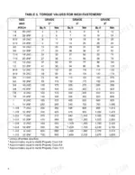
| Fastener Identification | 344-386 | Metric Fasteners, Inch Fasteners, Strength Identification, Torque Values, Thread Design |
Quick Reference Specifications
| Specification | Value | Page |
|---|---|---|
| Overhead guard capscrews torque | 66 N.m (48 lbf ft) | p. 2 |
| Counterweight to frame capscrews torque | 320 N.m (236 lbf ft) | p. 5 |
| Battery compartment clearance | 13 mm (0.5 in) | p. 39 |
| Minimum brush length | 3 mm (0.060 in) | p. 41 |
| Minimum brush seater stone length | 60 mm (2.5 in) | p. 43 |
| Maximum steering system pressure | 10.7 to 11.0 MPa (1,550 to 1,600 psi) | p. 108 |
| Steering chain tension | 7.35 to 11.00 mm (0.29 to 0.43 in) | p. 108 |
| Steering chain tension (movement) | 7.35 to 11.00 mm (0.29 to 0.43 in) | p. 108 |
| Maximum pressure for E2.00–3.20XM (E45–65XM) and N30XMH | 8.62 MPa (1250 psi) | p. 130 |
| Flange cover to motor housing screw torque | 5 to 8 Nm (45 to 70 lbf in) | p. 128 |
| Steering chain tension movement | 7.35 to 11.00 mm (0.29 to 0.43 in) | p. 131 |
| Master cylinder push rod clearance | 0.25 to 0.50 mm (0.010 to 0.020 in) | p. 138 |
Hyster A1.00XL–A1.50XL (A20XL–A30XL) Common Problems This Manual Covers
Hyster A1.00XL traction motor brushes worn short with burned, pitted, or worn commutator surface
Measure each brush and replace any shorter than 3 mm (0.060 in), as page 41 specifies. Use only Hyster approved brushes. Inspect the commutator for burns, pits and thrown solder. To seat new brushes, raise the drive wheels, wear eye protection, run the motor at low speed and keep your fingers clear of moving parts. Never use a seater stone shorter than 60 mm (2.5 in), per page 43.
Manual Section: Motor Maintenance p. 41Lift relief valve pressure reads off spec during hydraulic system control valve check
Warm the hydraulic oil to 55 to 65°C (130 to 150°F) before testing, as page 158 calls for. Check lift relief pressure against 20.7 MPa (3000 psi) and tilt relief against 15.5 MPa (2250 psi), the values listed on page 376. Adjust the relief valve following the control valve checks and adjustments. Confirm the tank is filled to the FULL mark (12.3 litre, 13 qt).
Manual Section: Hydraulic System p. 158Hydraulic steering motor pressure below maximum spec or steering chain tension out of adjustment
Before you remove any covers, disconnect the battery connector and tag it DO NOT CONNECT BATTERY, as page 83 directs. Test maximum steering system pressure against 10.7 to 11.0 MPa (1,550 to 1,600 psi) using the page 108 procedure. Some XM and XMS units carry lower limits on page 130, so confirm your model first. Check steering chain movement against 7.35 to 11.00 mm (0.29 to 0.43 in) and adjust it to that range.
Manual Section: Hydraulic Steering Motor p. 108Service brake drum worn past limit or brake pedal free travel out of adjustment
Put the truck on blocks on a solid, level surface, using blocks or stands with enough capacity, per page 118. Then pull the wheel and drum. Measure the drum inside diameter and replace the drum if it exceeds 182.27 mm (7.11 in), the page 141 limit. Torque the wheel nuts to 140 N.m (104 lbf ft). Check pedal free travel against 1 to 4 mm (0.04 to 0.16 in).
Manual Section: Brake System p. 141Battery electrolyte overheating on charge or specific gravity low after full charge cycle
Check electrolyte temperature against the 49°C (120°F) limit on page 261. Verify the temperature rise stays within 14°C (25°F) during an eight hour charging period, per page 263. Test each cell with a hydrometer against 1.265 to 1.310 at 25°C (77°F). Keep tools and metal objects off the battery top while you work, as page 119 warns, because they can short the battery.
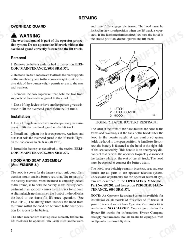
Manual Section: Battery Maintenance p. 261Hood battery restraint latch worn and not locking hood to frame in closed position
Inspect the sliding latch at the front of the hood following page 2. Verify the latch is not worn and fully engages the frame when the hood closes. If the latch does not lock the hood in the closed position, do not operate the truck. Correct the latch before the truck goes back into service, because the hood holds the battery in its compartment.
Manual Section: Parts of the Frame p. 2Frequently Asked Questions
What are the torque specifications for Hyster wheel, mast, tilt-cylinder, and drive-axle fasteners?
Torque specifications vary by component. For example, the counterweight capscrews require 320 N.m (236 lbf ft), overhead guard capscrews require 66 N.m (50 lbf ft), and wheel lug nuts for the Speth MDU require 155 N.m (115 lbf ft). For mast components, the carriage hook capscrews require 165 N.m (122 lbf ft). p. 378
How do you bleed air from Hyster tilt cylinders and hydraulic lines?
To bleed air from the tilt system, operate the hydraulic system by putting a capacity load on the forks and raising/lowering the load several times. Then, lower the load and tilt the mast forward and backward several times to check for leaks and ensure air is removed. p. 339
What is the procedure for adjusting the brake pedal on later model Hyster lift trucks?
For later models, adjust the brake pedal so that it moves down 1 to 4 mm (0.04 to 0.16 in) before the push rod touches the piston. Apply Loctite to the threads and tighten the jam nut against the clevis. p. 144
What is the correct procedure for checking the lift chain tension?
The tension is correct when the chain moves 7.35 to 11.00 mm (0.29 to 0.43 in) when pushed. Ensure the tension is the same on each chain of the chain set by pushing on both chains at the same time. p. 361
What is the recommended procedure for cleaning the hydraulic tank breather?
The hydraulic tank breather is fastened to the side of the hydraulic tank filter. Inspect the breather and clean or replace it when it is dirty and will not permit the easy passage of air. p. 364
What format is this Hyster A1.00XL manual in?
A single searchable PDF file of 386 pages, downloadable right after payment. Nothing ships, nothing waits in the mail.
Can I print this Hyster A1.00XL manual?
Yes. Many buyers print one chapter at a time for their own shop and keep the rest on a tablet.



Reviews
There are no reviews yet.