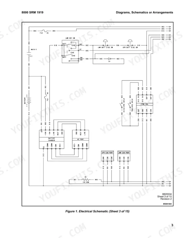
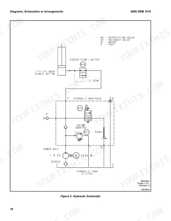
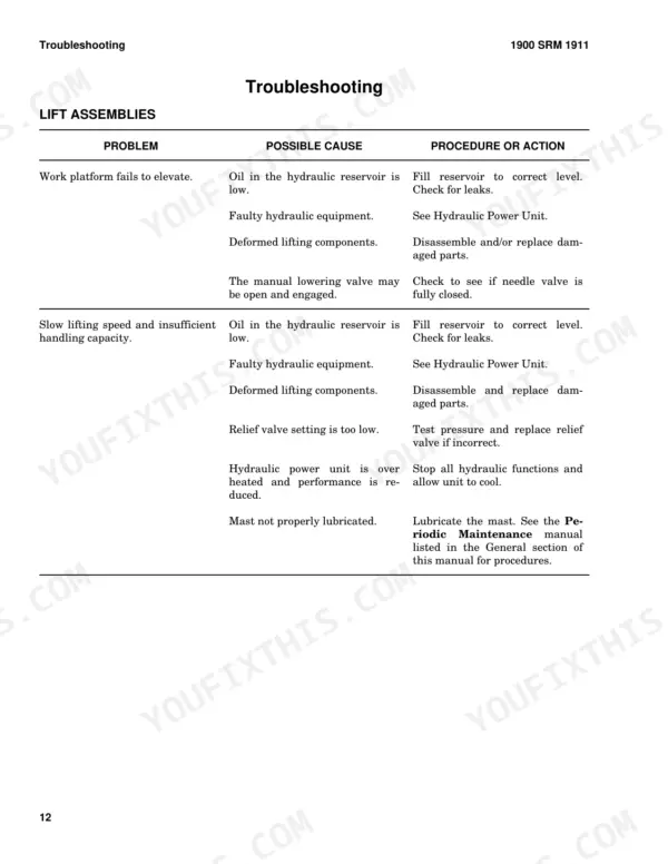
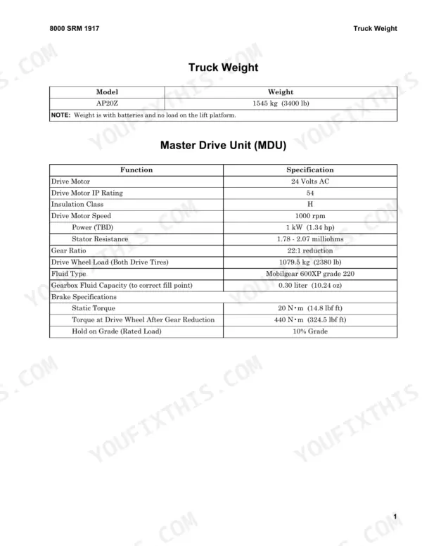
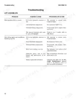
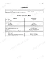
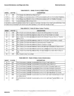
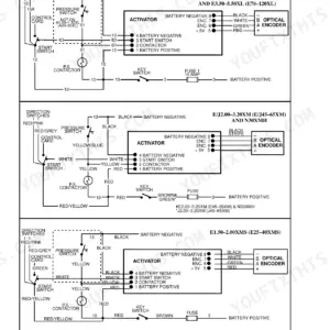
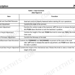
When a Hyster AP20Z logs a diagnostic trouble code, this 390-page service manual for the aerial work platform, OEM ID 4131885, gives you the factory diagnostics behind it. As a Hyster AP20Z service manual PDF, it pairs electrical schematics with controller pinouts and a trouble code list, so a code leads straight to the circuit it points at. Hydraulic schematics map the power unit and lift assemblies, while the hydraulic troubleshooting, relief valve pressure check and lift cylinder seal kit installation are written out in full. Read the brake coil against 18.5 to 21.3 ohms at 20°C (68°F). Pump pressure peaks at 21.03 MPa (3050 psi) continuous. Your job might be removing the lower controls panel mounting bracket, or discharging the capacitors before welding. Bookmarks sort the file by section, and the pages print cleanly when you want a working copy of the schematics.
What's Inside This Manual
| System | Pages | Key Topics |
|---|---|---|
| General | 7-8 | Description, Features, Working Near Power Lines |
| Special Precautions | 9-10 | Discharging the Capacitors, Welding |
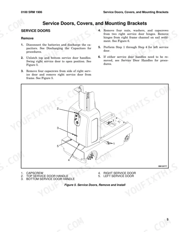
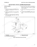
| Service Doors, Covers, and Mounting Brackets | 11-17 | Service Doors (Remove, Install), Service Door Handles (Remove, Battery Cover (Remove, Mast Cylinder Cover (Remove |
| Caster Wheels | 18 | Remove, Install |
| Battery Compartment | 19 | |
| Painting Instructions | 20 | |
| Label Replacement | 21-23 | Warning Labels, Caution Labels, Nameplate, Label Locations |
| Operator Compartment | 27-46 | Operator Compartment Removal, Operator Door Disassembly, Mid-Mount Tray, Operator Compartment Installation |
| Master Drive Unit | 47-68 | Master Drive Unit Removal, Master Drive Unit Installation, Brake System, Steering System |
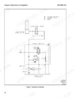
| Hydraulic System | 69-90 | Hydraulic Power Unit, Relief Valve Pressure Check, Hydraulic Troubleshooting, Lift Assemblies |
| Lift Cylinders | 91-108 | Lift Cylinder Removal, Lift Cylinder Disassembly, Seal Kit Installation, Torque Specifications |
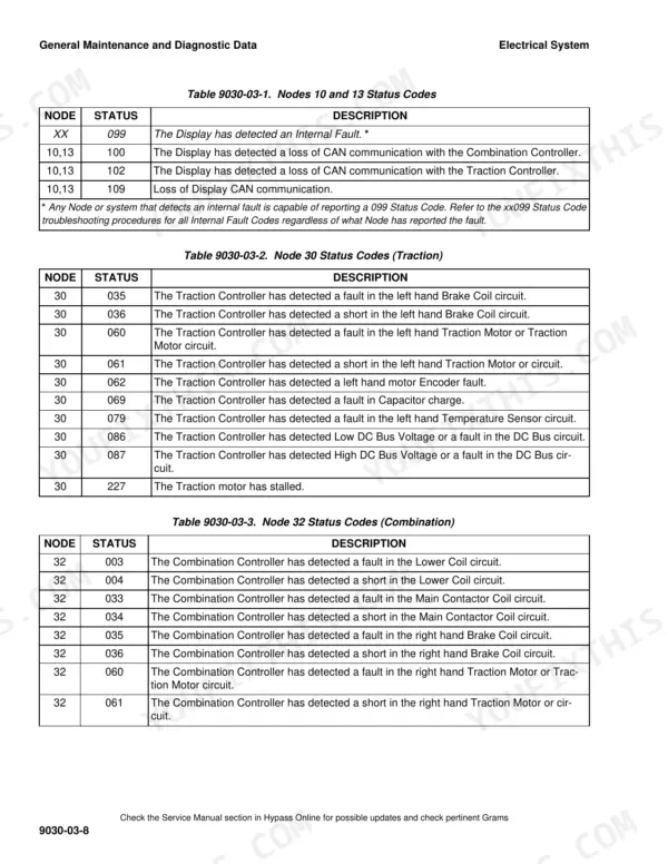
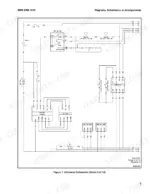
| Electrical System and Diagnostics | 109-154 | Electrical System Features, Controller Pinouts, Diagnostic Trouble Codes, Electrical Schematics |
| Aerial Work Platform Battery | 155-180 | Chemical Reaction in a Cell, Battery Ratings, Where to Charge Batteries |
| Mast Repair | 181-212 | Clean and Inspect, Lateral Mast Adjustment, Vertical Mast Adjustment |
| Metric and Inch (SAE) Fasteners | 213-232 | Threaded Fasteners, Fastener Torque Tables, Conversion Table |
| Capacities and Specifications | 233-246 | Truck Weight, Electrical Specifications, Mast Speeds |
| Periodic Maintenance | 247-284 | How to Tow the Lift, Maintenance Schedule, Hydraulic Oil Analysis |
| Diagrams | 285-308 | Electrical Schematic, Hydraulic Schematic |
| Controller Diagnostics | 309-390 | General Maintenance and Diagnostic Data, Warning Codes, Diagnostic Trouble Codes |
Quick Reference Specifications
| Specification | Value | Page |
|---|---|---|
| Master drive unit weight | 23 kg (51 lb) | p. 58 |
| Gear box capscrew torque | 90 N·m (66 lbf ft) | p. 59 |
| Brake coil resistance at 20°C (68°F) | 18.5 to 21.3 ohms | p. 65 |
| Hydraulic Pump Displacement | 1.6 cc/rev | p. 240 |
| Hydraulic Pump Max Continuous Pressure | 21.03 MPa (3050 psi) | p. 240 |
| Excess Flow Protector Fitting | 85 to 94 N•m (63 to 69 lbf ft) | p. 105 |
| Fitting (Hydraulic Tube Fitting to Excess Flow Protector Fitting) | 55 to 60 N•m (40 to 44 lbf ft) | p. 105 |
| Gland | 340 to 410 N•m (251 to 302 lbf ft) | p. 105 |
| Mast Proximity switch gap | 8 mm (0.315 in.) | p. 122 |
| Operator Gate Proximity switch gap | 5 mm (0.197 in.) | p. 16 |
| Traction Controller mounting capscrews torque | 7 to 8 N·m (62 to 71 lbf in) | p. 144 |
| Traction Motor Controller Mounting Screws Torque | 7 to 8 N•m (62 to 71 lbf in) | p. 244 |