
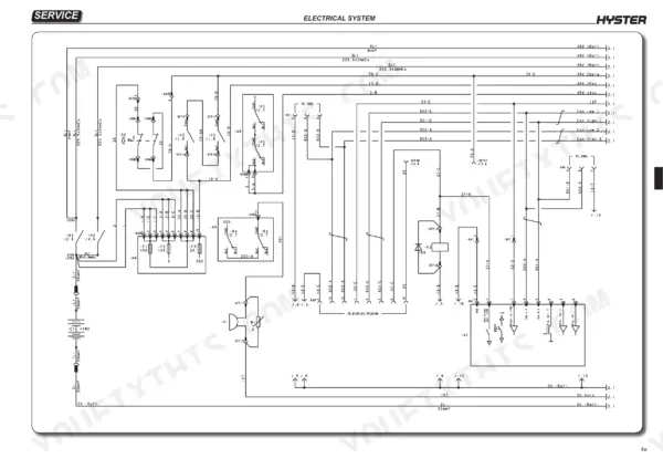
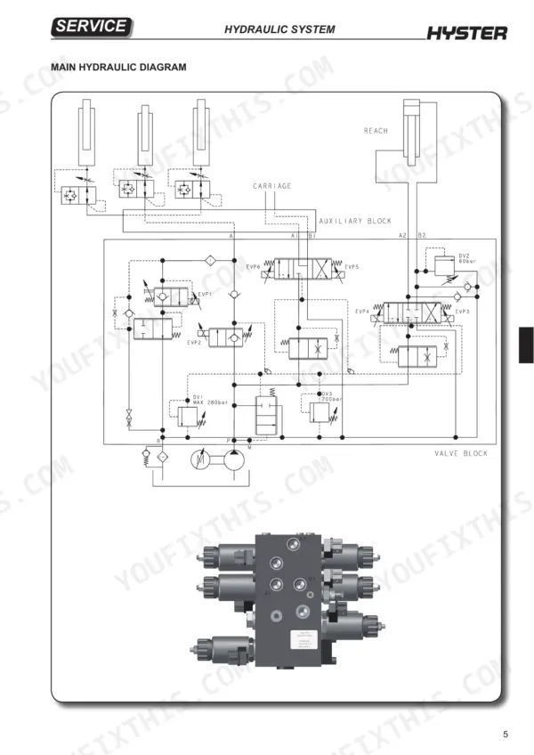
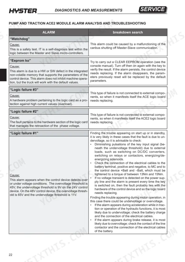
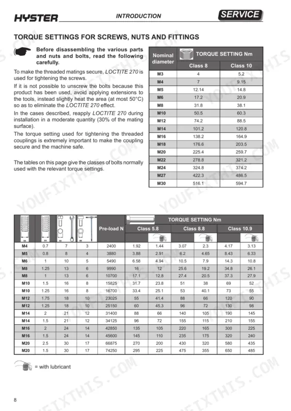
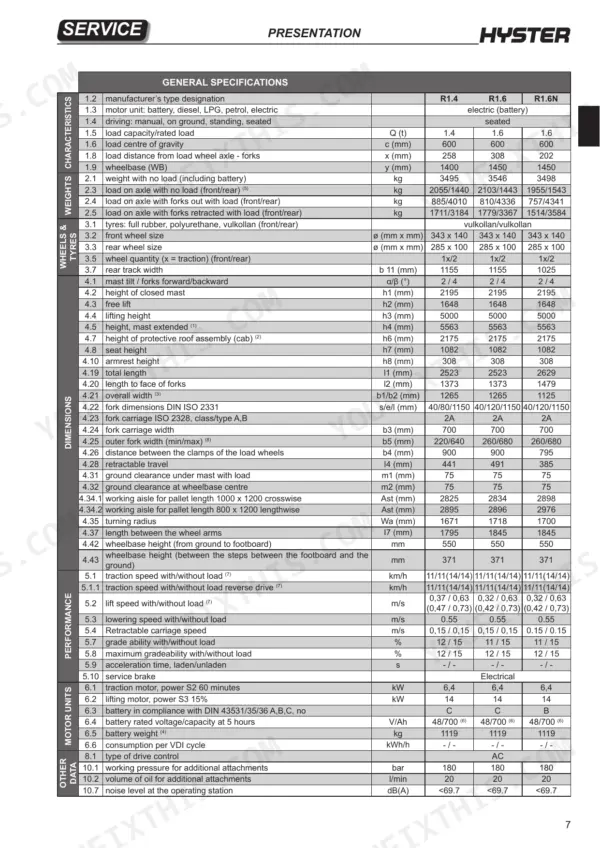
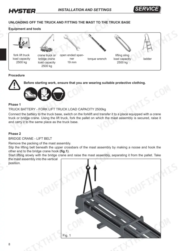
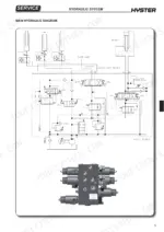
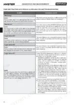
Across 473 pages, the Hyster R1.4 service manual PDF (OEM ID 4065749) gives you one factory source for servicing seven retractable truck variants in the R1.4 to R2.5 series. Wiring diagrams trace the armrest, pedal unit and main panel controls, while hydraulic diagrams lay out solenoid valve operation, the pressure relief valve, cylinders and the lift pump. The diagnostics chapter walks through the tester menu, alarm analysis and breakdown search, then module replacement procedures cover the ACE2 inverter, EPS ACW and VCM units. Torque the solenoid valve body retaining nut to 29 Nm. On the middle lift cylinder, the bush takes 353 to 380 Nm. Your scheduled maintenance round, from chains and forks to electromagnetic brake liners and outriggers height, is laid out in the routine maintenance chapter. Bookmarked and text-searchable, this copy is a one-time purchase that stays yours for as long as you run the truck.
What's Inside This Hyster R1.4–R2.5 Manual
| System | Pages | Key Topics |
|---|---|---|
| Technical Information | 1 | Hyster Service Network, Specialized Technicians, Product Support Group |
| Introduction | 2-12 | General Safety Rules |
| Presentation | 13-24 | Truck Presentation, Views of the Truck, Truck and Load Identification Data, Truck Identification Data Plate, Residual Load Plate |
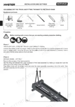
| Installation and Settings | 25-44 | Truck Assembly, Battery Installation, Oil Reservoir, Fork Assembly, Load Rack Assembly, Contrasting Roller Assembly |
| Diagnostics and Measurements | 45-108 | Module Connectors, Tester Menu, Breakdown Search, Warning Memorization, Alarm Analysis, Troubleshooting |
| Electrical Wiring Diagrams and Controls | 109-131 | Wiring Diagrams, Armrest Controls, Pedal Unit Controls, Main Panel Controls |
| Standard and Premium Display | 132-156 | Standard Display Keypad, Premium Display, Graphic Screen Icons, Display Brightness Control |
| Menu Screens and Parameter Settings | 157-173 | Main Menu 1, Main Menu 2, Parameter Setting, Access Code Programming, Software Version |
| Module Replacement and Electrical Components | 174-184 | ACE2 Inverter Replacement, EPS ACW Module Replacement, VCM Module Replacement, Horn Replacement |
| Contactors, Fuses, and Cooling Fans | 185-196 | Contactor Replacement, Fuse Replacement, Motor Compartment Cooling Fan, Premium Display Replacement |
| Sensors and Pedals | 197-211 | Side Shift Position Sensor, Pallet Presence Sensor, Tilt Position Sensor, Accelerator and Brake Pedals |
| Truck Functions and Configuration | 212-328 | Height Pre-Selector, Traction Blocks, Speed Reduction, Braking Systems, Steering System Configuration |
| Hydraulic System | 329-384 | Hydraulic Diagrams, Solenoid Valve Operation, Pressure Relief Valve, Cylinders, Lift Pump, Hydraulic Pipes |
| Truck Base Mechanics | 385-410 | Traction Wheel Components, Drive Wheel, Load Wheel Components, Battery Block, Traction Motor, Steering Motor, Retractable Carriage |
| Mast Assembly Mechanics | 411-431 | Mast Characteristics, Mast Elevation, Bearing Replacement, Chains, Chain Tensioner, Chain Sheaves |
| Small Fork Mast Mechanics | 432-437 | Fork Carriage, Sliding Blocks, Bearing Replacement |
| Reduction Gear | 438-447 | Reduction Unit Components, Reduction Unit, Traction Motor Drive Shaft Radial O-Ring, Wheel Shaft Radial O-Ring, Reduction Unit Oil |
| Braking System | 448-455 | Traction Motor Electromagnetic Brake, Load Wheel Electromagnetic Brake, Release Braking, Direction Reversal Braking, Emergency Braking, Parking Brake |
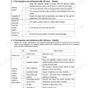
| Routine Maintenance | 456-473 | Oils and Lubricants, Cleaning Products, Scheduled Maintenance, Outriggers Height, Screws and Bolts, Chains, Forks, Electromagnetic Brake Liners |
Quick Reference Specifications
| Specification | Value | Page |
|---|---|---|
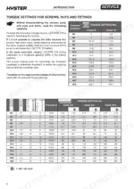
| Torque setting for M3 Class 8 screw | 4 Nm | p. 8 |
| Torque setting for M3 Class 10 screw | 5.2 Nm | p. 8 |
| Middle lift cylinder bush tightening torque | 353-380 Nm | p. 373 |
| Side lift cylinders bush tightening torque | 358 Nm | p. 373 |
| Solenoid valve body retaining nut torque | 29 Nm | p. 356 |
| Pressure relief valve installation torque | 10 to 12 Nm | p. 353 |
| Pump to flange tightening torque | 45 Nm | p. 378 |
| Tightening Torque: Mast to Retractable Carriage | 300-330 Nm | p. 33 |
| Tightening Torque: Mast Assembly Side Blocks | 88-97 Nm | p. 33 |
| Tightening Torque: Traction Wheel Retaining Nuts | 130 Nm | p. 388 |
| Tightening Torque: Reduction Unit to Plate | 88 Nm | p. 442 |
| Tightening Torque: Brake Disk Screws | 25 Nm | p. 391 |
Hyster R1.4–R2.5 Common Problems This Manual Covers
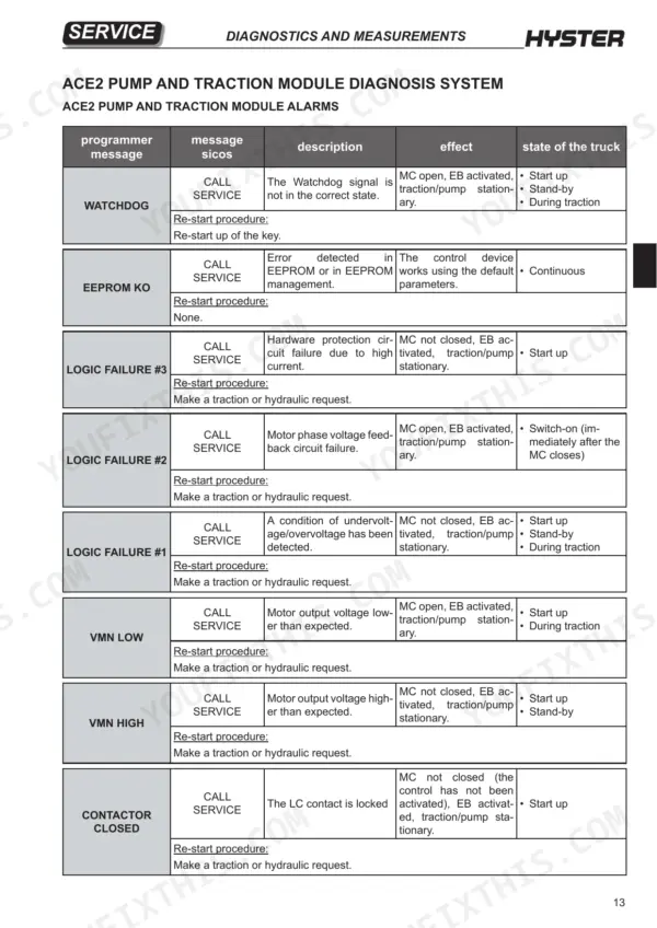
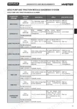
Hyster R1.6 retractable truck ACE2 alarm CONTACTOR CLOSED or CONTACTOR OPEN, truck stationary with brake applied
Check the display code. CONTACTOR CLOSED means the LC contact is locked. CONTACTOR OPEN means the MC coil was energized but the contactor never closed (pages 57 and 58). Make a traction or hydraulic request to retry, and call service if it returns. If you open the electric compartment, disconnect the battery and discharge the capacitors first, and never file or lubricate the contactor contacts (page 457).
Manual Section: ACE2 Pump and Traction Module Alarms p. 57Traction slows or cuts out when hot with TH. PROTECTION or MOTOR TEMPERAT. alarm displayed
Check which alarm is active. TH. PROTECTION means the controller reached 85°C, and current tapers to 0A at 105°C. MOTOR TEMPERAT. means the motor sensor is open or above 150°C, so maximum current is halved and speed reduced (page 58). Verify trip frequency in Main Menu 1 Alarms, which stores the last 20 warnings (page 56). Call service if it persists.
Manual Section: ACE2 Pump and Traction Module Alarms p. 58Truck runs at reduced speed with BATTERY LOW alarm displayed on the ACE2 module
Check the battery state of charge. BATTERY LOW triggers at 10% or less when the BATTERY CHECK parameter is set above 0, and it halves maximum current and reduces speed (page 58). Recharge the battery, then cycle the key to clear the alarm. Never check the charge with jumpers or metal items across the terminals, and do not short-circuit the terminals (page 5).
Manual Section: ACE2 Pump and Traction Module Alarms p. 58Traction or pump motor will not start with VACC NOT OK or VACC OUT RANGE alarm
Check that the accelerator is fully released. VACC NOT OK sets when the potentiometer reads above its recorded minimum while the direction switches are off (page 59). VACC OUT RANGE means the input left the Vacc_min to Vacc_max window acquired with the PROGRAMM VACC function (page 62). Make a traction or hydraulic request to retry, and call service if it returns.
Manual Section: ACE2 Pump and Traction Module Alarms p. 59Truck refuses to drive after key-on with INCORRECT START TRACT or INCORRECT START PEDAL alarm
Check the operator's start sequence first. Both alarms flag an incorrect starting sequence and hold the traction/pump motor stationary (pages 59 and 63). For INCORRECT START PEDAL, release the pedal and make a new traction request. For INCORRECT START TRACT, make a fresh traction or hydraulic request. A warning service screen also appears after an incorrect operator sequence (page 193).
Manual Section: ACE2 Pump and Traction Module Alarms p. 59Electromagnetic brake stays applied with COIL SHOR. EB or AUX DRIV. OPEN alarm displayed
Verify the exact code on the display. COIL SHOR. EB is a short circuit on the EB coil. AUX DRIV. OPEN means the AUX coil driver has failed and cannot operate the brake (pages 63 and 64). Make a traction or hydraulic request to retry. If the alarm comes back, call service.
Manual Section: ACE2 Pump and Traction Module Alarms p. 63Frequently Asked Questions
How do I reset the Hyster R1.4 error code?
To reset an error code, you must perform the re-start procedure specified for that particular alarm. For most alarms, this involves turning the key switch to OFF and then back to ON, or making a new traction or hydraulic request. Refer to the 'ACE2 PUMP AND TRACTION MODULE ALARMS' table on page 57 for the specific re-start procedure required for each alarm code. p. 57
How do I clear Hyster R1.4, R1.6, R2.0, and R2.5 fault codes?
You can clear saved alarms using the 'CLEAR ALARMS' function in the 'MAIN MENU 2' of the display. When the 'CLEAR ALARMS?' screen appears, use the direction buttons to select 'YES' and press 'ENTER' to delete the saved alarms. p. 170
What are the Hyster R1.4–R2.5 traction and hydraulic controller replacement specs?
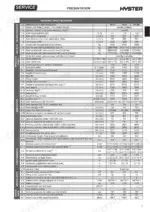
The ACE2 traction and pump modules are designed for 24V to 96V systems. The 48V-350A model provides 350A (RMS) for 3 minutes, while the 48V-400A model provides 400A (RMS) for 3 minutes. The operating frequency is 8 kHz, and the maximum inverter temperature is 75°C. p. 295
What is the torque setting for the mast assembly screws on the Hyster R1.4–R2.5?
The screws fastening the mast to the retractable carriage must be tightened to a torque of 300 to 330 Nm. p. 464
What is the tightening torque for the drive wheel nuts on the Hyster R1.4–R2.5?
The traction wheel retaining nuts must be tightened using a torque wrench to a torque of 130 Nm. p. 388
How is this Hyster R1.4 Service Manual delivered?
A single searchable PDF file of 473 pages, downloadable right after payment. Nothing ships, nothing waits in the mail.
Does this Hyster R1.4 manual allow printing?
Yes. Many mechanics print the section they need for their own shop and bring it to the bench.


Reviews
There are no reviews yet.