
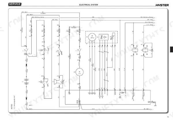
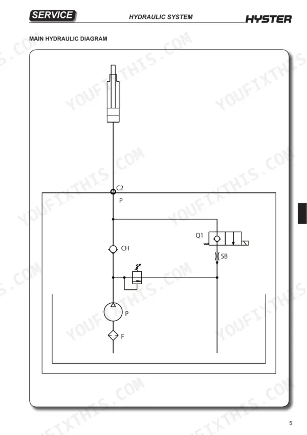
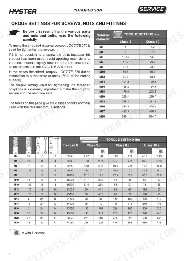
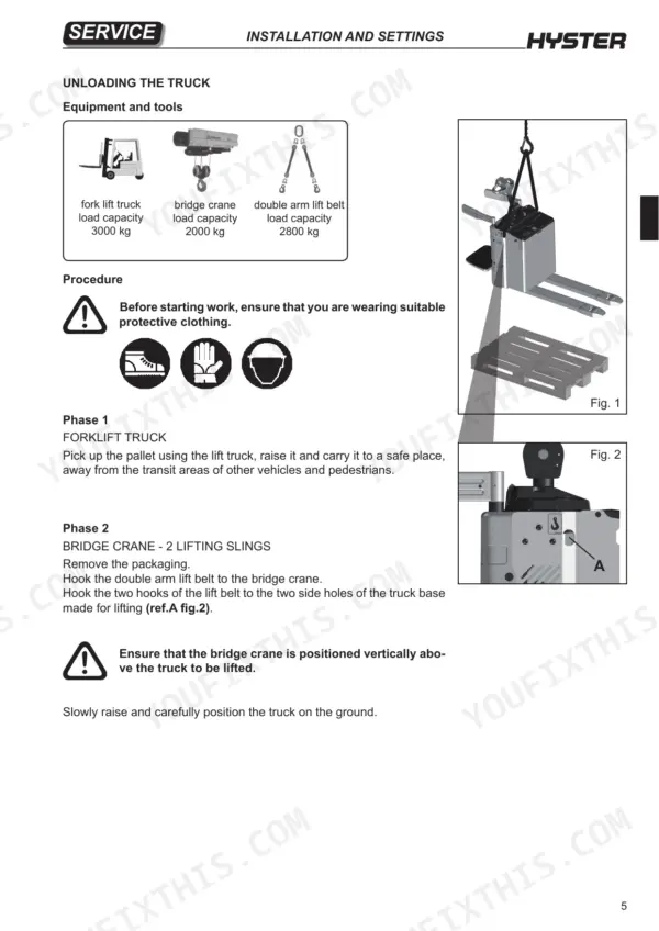
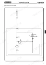
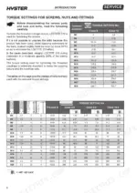
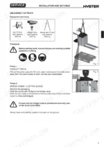
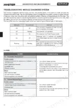
Across 209 pages, the Hyster P2.0SE service manual PDF (OEM ID 4061502) covers repair and maintenance of this battery-powered fork lift truck with factory data. Wiring diagrams trace the tiller board, traction module and steering sensor circuits, while hydraulic schematics show the pressure relief valve, cartridge solenoid valve and lift pump. Fault finding runs through the Combi Module's Monitor and Faults menus, module connectors and electrical component measurements; later chapters handle the drive wheel and load wheels, reduction unit removal and disassembly, and electromagnetic brake removal and adjustment. Rig the 24/210 V/Ah battery for 201-223 kg on a lifting tackle rated at 1000 kg, and torque the reduction unit to chassis mounting screws to 25 Nm. Setting the battery voltage after installation is a listed job in your Installation and Settings chapter. Every page prints cleanly as a working copy.
What's Inside This Hyster P2.0SE Manual
| System | Pages | Key Topics |
|---|---|---|
| Introduction | 2-12 | General Safety Rules |
| Presentation | 13-18 | Truck Presentation, Views of the Truck, Truck and Load Identification Data, Truck Identification Data Plate, Truck Serial Number Punching and Location of Documentation |
| Installation and Settings | 19-30 | Before Installation, Weight Table, Truck Assembly, List of Materials Received From the Dealer, Unloading the Truck, Topping Up the Oil Reservoir, Installation of the Battery |
| Diagnostics and Measurements | 31-56 | Module Connectors, Combi Module, Monitor Menu, Faults Menu, Controller Information, Electrical Component Measurements |
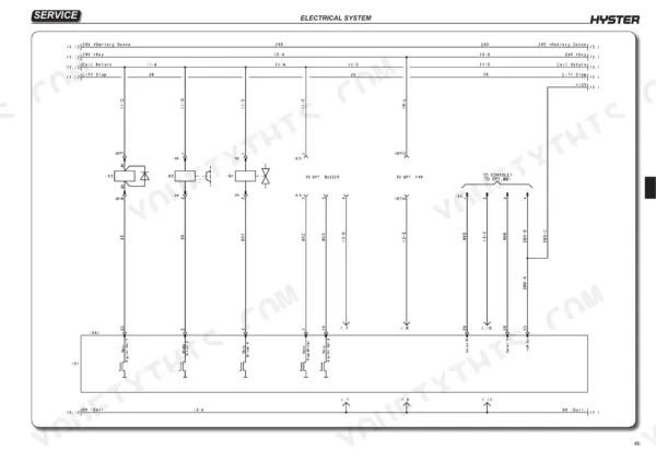
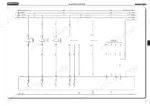
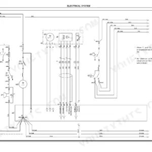
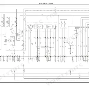
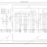
| Electrical System | 57-111 | Electrical Wiring Diagrams, Tiller Board, Battery Charge Level Indicator, Traction Module, Panel Sensors, Steering Sensor |
| Hydraulic System | 112-139 | Pressure Control Valves, Directional Valves, Pressure Switches, Pressure Relief Valve, Cartridge Solenoid Valve, Lift Pump |
| Mechanics | 140-183 | Drive Wheel, Pivoting Wheel Assembly, Footboard, Side Panels, Load Wheels, Linkage |
| Reduction Unit | 184-195 | Reduction Unit Components, Reduction Unit Removal, Reduction Unit Disassembly, Reduction Unit Oil |
| Braking System | 196-201 | Electromagnetic Brake Components, Braking Systems, Electromagnetic Brake Removal, Electromagnetic Brake Adjustment |
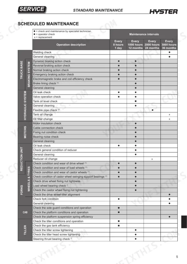
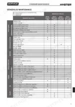
| Standard Maintenance | 202-209 | Oils, Lubricants, Cleaning Products, Scheduled Maintenance |
Quick Reference Specifications
| Specification | Value | Page |
|---|---|---|
| Maximum air pressure for cleaning | 1 bar | p. 4 |
| Battery weight (min/max) | 201-223 kg | p. 20 |
| Battery weight | 288 kg | p. 17 |
| Reduction unit to chassis mounting screw torque | 25 Nm | p. 181 |
| Pump to flange tightening torque | 5 Nm | p. 137 |
| T handle hex key size | 2.5 - 4 mm | p. 106 |
| Seal carrier bush tightening torque | 275 Nm | p. 131 |
| Traction motor power (S2 60 minutes) | 2 kW | p. 17 |
| Pressure relief valve installation torque | 13 Nm | p. 122 |
| Pressure relief valve calibration torque | 20-22 Nm | p. 123 |
| Solenoid valve retaining screws torque | 39-51 Nm | p. 125 |
| Lifting cylinder seal carrier bush torque | 275 Nm | p. 131 |
Hyster P2.0SE Common Problems This Manual Covers
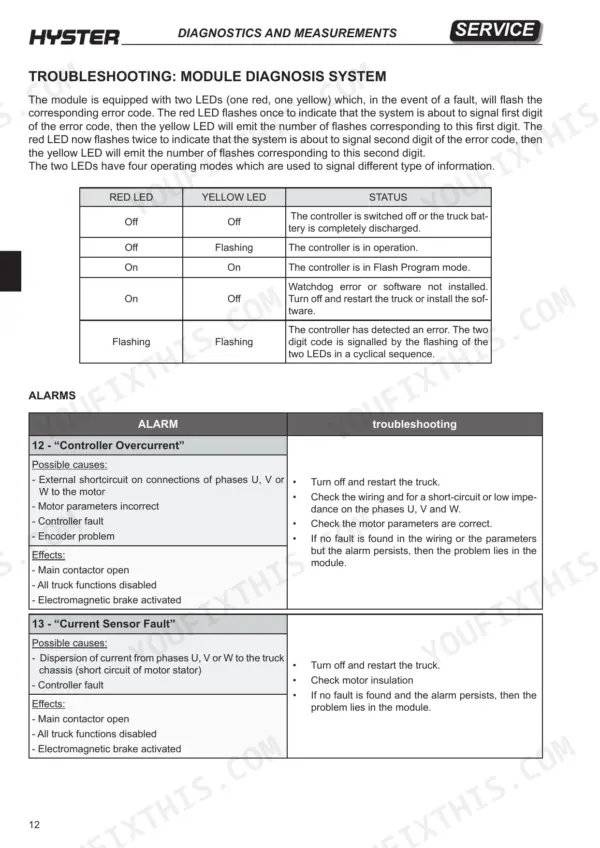
Hyster P2.0SE alarm 12 controller overcurrent, main contactor opens and all truck functions disabled
Turn off and restart the truck first. If alarm 12 returns, disconnect the battery (page 5) and discharge the capacitors before touching the electric compartment (page 203). Check the wiring for a short circuit or low impedance on phases U, V and W, and verify the motor parameters. If wiring and parameters check out and the alarm persists, the fault is in the module (page 42).
Manual Section: Module Diagnosis System Alarms p. 42Alarm 13 current sensor fault with electromagnetic brake applied and all truck functions disabled
Cycle the key off and on. If alarm 13 holds, disconnect the battery (page 5) and discharge the capacitors (page 203). Check traction motor insulation for current leaking from phases U, V or W to the chassis, which points to a shorted motor stator; use the motor insulation resistance check in Electrical Component Measurements. If insulation is good and the alarm persists, the module is at fault (page 42).
Manual Section: Module Diagnosis System Alarms p. 42Battery undervoltage cutback alarm 23 or severe undervoltage alarm 17 with reduced drive
Check MAIN MENU MONITOR / Battery / Capacitor Voltage and bring it back above the minimum value; a discharged battery alone will trigger alarm 23 (page 44). Verify the battery parameters. Disconnect the battery before working on the wiring (page 5), then check battery wiring for high resistance, the fuse on the key switch positive feed, and whether the main contactor closes. A persisting alarm points to the module (page 43).
Manual Section: Module Diagnosis System Alarms p. 43Controller overtemp cutback alarm 22 with reduced drive and weaker braking effect
Check MAIN MENU MONITOR / Controller / Temperature. Above 85°C, release the tiller controls, remove all loads, switch off, wait a few minutes and restart (page 44). Above 95°C the truck shuts down on alarm 16 (page 43). Check whether the truck is being overloaded. Discharge the capacitors before inspecting the electric compartment (page 203), then verify the module is installed correctly. If everything checks out and the alarm persists, replace the module.
Manual Section: Module Diagnosis System Alarms p. 44Main contactor did not close alarm 39, all truck functions disabled and brake activated
Disconnect the battery (page 5) and discharge the capacitors (page 203). Check the main contactor power wiring, clean the connectors and confirm the fastons are tight. Inspect for oxidised, burned or disconnected contacts, but never file or lubricate contactor contacts (page 203). Check the fuse on the key switch positive feed, reconnect, read MONITOR / Battery / Capacitor Voltage and restart. If the alarm persists, the module is at fault (page 48).
Manual Section: Module Diagnosis System Alarms p. 48Coil 3 driver open/short alarm 33 on the hydraulic pump contactor, pump contactor driver stopped
Disconnect the battery before touching the wiring (page 5) and discharge the capacitors (page 203). Check the hydraulic pump contactor coil wiring on pin 4 for damage, clean the connector and contacts, then switch the truck off and back on. Do not file or lubricate the contactor contacts (page 203). If the wiring is sound and alarm 33 persists, the module is faulty (page 46).
Manual Section: Module Diagnosis System Alarms p. 46Frequently Asked Questions
How do I clear stored status codes on a Hyster P2.0SE?
To clear the stored status codes, open the FAULTS MENU and select the CLEAR FAULT HISTORY option. This will reset the alarms log. p. 40
How do I reset the Hyster P2.0SE battery discharge indicator?
To reset the low battery charge indicator, you must recharge the battery. When the recharge reaches 100%, the indicator is automatically reset, and the fork lift system is restored. p. 76
What are the replacement specifications for the COMBI traction/hydraulic controller on the Hyster P2.0SE?
The controller is designed for 24V operation with a maximum inverter current of 200A (RMS) for 2 minutes. It operates at a PWM frequency of 10 kHz and supports external temperature limits from -40°C to 50°C. p. 96
What torque is required to tighten the reduction unit to the chassis on the Hyster P2.0SE?
When installing the reduction unit, the screws securing it to the chassis must be tightened using a torque wrench to a torque of 25 Nm. p. 188
What is the correct oil type and quantity for the reduction unit?
The reduction unit requires 1.4 litres of ESSO UNIFARM 15W-40 oil for both standard and cold store applications. p. 194
Is this Hyster P2.0SE manual a PDF I download?
A single searchable PDF file of 209 pages, downloadable right after payment. Nothing ships, nothing waits in the mail.
Am I free to print this Hyster P2.0SE Service Manual?
Yes. Print the pages or sections you need for your own shop use. Any standard printer works.


Reviews
There are no reviews yet.