
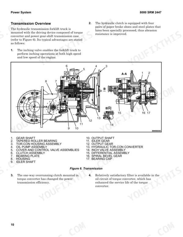
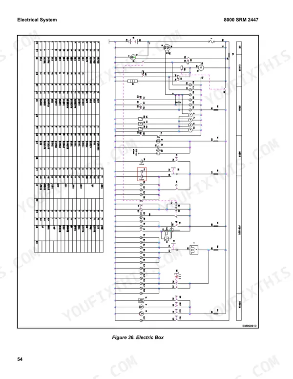
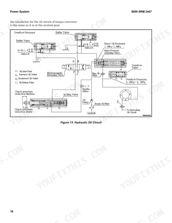
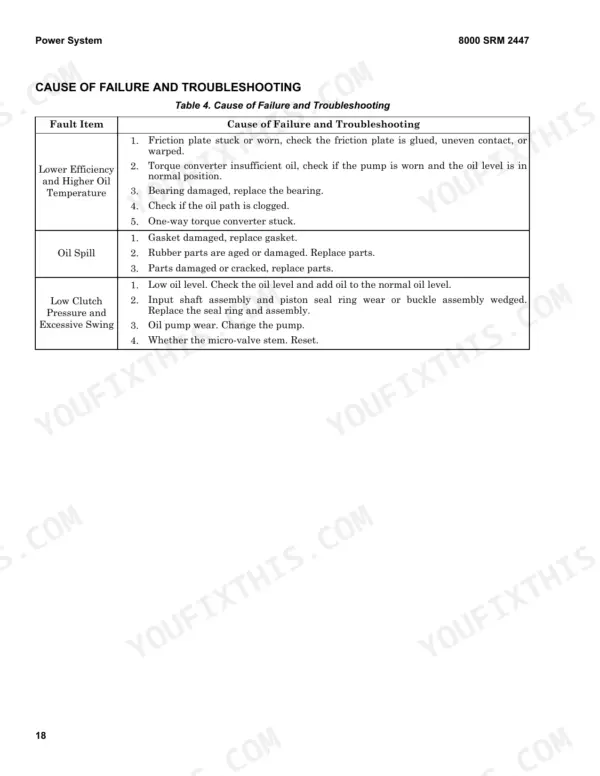
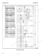
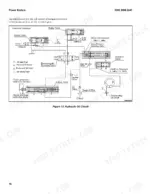
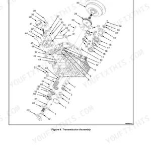
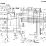
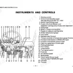
Servicing a Hyster F5.0UT or F100UT forklift truck, from the fuel tank to the electrical box, fits into 66 pages of factory data under OEM ID 4310285. Hydraulic schematics in this Hyster F5.0UT service manual PDF trace the main oil pump, multi-way valve, tilt auto-locking valve and the lifting and tilting cylinders, while the transmission chapter breaks down the torque converter, hydraulic clutch and inching valve. Wiring gets the same treatment, with electrical schematics set beside fault checks for a truck that will not start. Refill the transmission with 8 liters of oil, and torque wheel nuts to 480 to 560 N·m (354 to 413 lbf ft). Perhaps your job is tracing the hydraulic oil circuit through the transmission case; the schematic and oil inlet/outlet connection location pages show where each line enters and exits. Bookmarks travel with the file, wherever your truck sits.
What's Inside This Hyster F5.0UT, F100UT Manual
| System | Pages | Key Topics |
|---|---|---|
| Forklift Truck Main Parts | 1-5 | Transmission System, Torque Converter, Hydraulic Transmission Case, Speed Reducer, Speed Differential, Steering System |
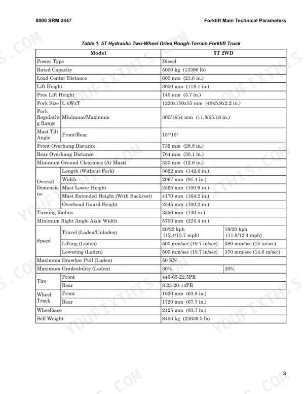
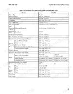
| Forklift Main Technical Parameters | 6-8 | Main Technical Parameters |
| Power System | 9-12 | Engine System (Engine Overview, Fuel System, Fuel Tank) |
| Transmission | 13-22 | Hydraulic Transmission Case and Torque Converter (Transmission Overview, Hydraulic Clutch, Control Valve) |
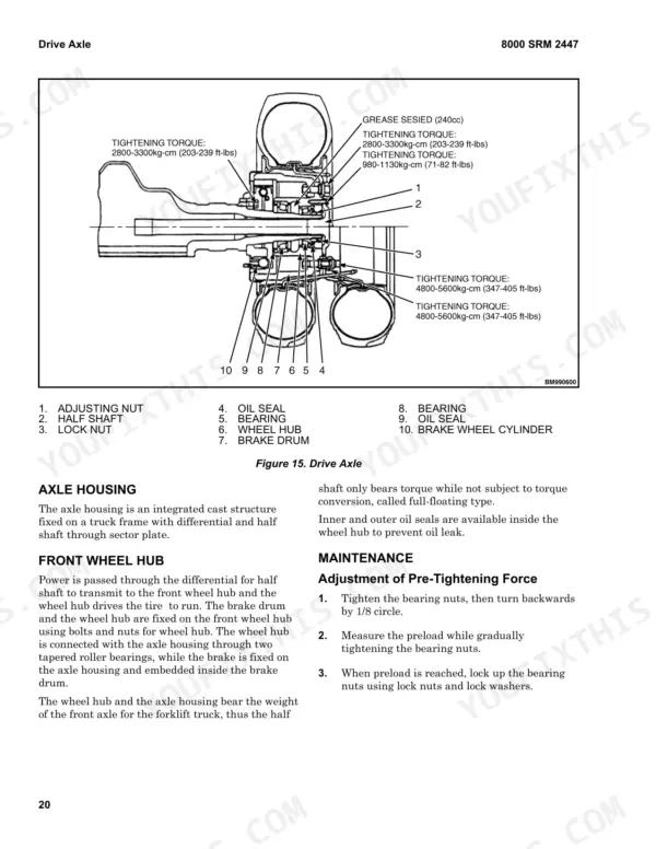
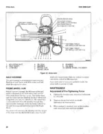
| Drive Axle | 23-25 | Overview, Axle Housing, Front Wheel Hub, Maintenance (Pre-Tightening Force, Wheel Mounting Sequence, Tire Installation, Installation of Double Tire) |
| Steering System | 26-32 | Overview (Fully Hydraulic Steering Gear Assembly, Steering Cylinder, Examination After Reassembly of Steering System) |
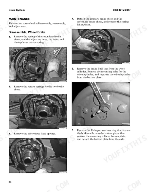
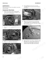
| Brake System | 33-42 | Overview (Brake Master Cylinder, Wheel Brake, Automatic Clearance Regulator) |
| Hydraulic System | 43-54 | Overview (Main Oil Pump, Bypass Valve, Multi-Way Valve) |
| Lifting System | 55-56 | Safety Procedures When Working Near Mast (Carriage, Lifting Chain) |
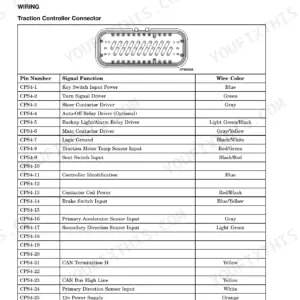
| Electrical System | 57-60 | Overview (Electrical Box, Battery, Electrical Schematics) |
| Drive, Operation, and Routine Maintenance of Forklift Truck | 61-66 | Transporting the Forklift Truck, Towing, Long-Term Storage of Forklift Truck, Maintenance Procedures Prior to Operation, Cooling System |
Quick Reference Specifications
| Specification | Value | Page |
|---|---|---|
| Battery Voltage/Capacity | 2x24/80 V/Ah | p. 8 |
| Wheel nut tightening torque | 480~560 N•m (354~413 lbf ft) | p. 25 |
| Wheel hub torque | 206-235 N·m (151.9-173.3 lbf ft) | p. 32 |
| Fuel Tank Capacity | 108 liter | p. 9 |
| Transmission Oil Capacity | 8 liter | p. 13 |
| Hydraulic System Operating Pressure | 20 MPa | p. 8 |
| Tire Pressure | 0.55 MPa | p. 23 |
| Steering Wheel Diameter | 360 mm | p. 26 |
| Brake Pedal Play | 45 mm | p. 37 |
| Wheel Cylinder Diameter | 31.75 mm | p. 33 |
| Brake Shoe Thickness | 11 mm | p. 39 |
| Multi-Way Valve System Pressure | 19 MPa | p. 43 |
Hyster F5.0UT, F100UT Common Problems This Manual Covers
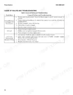
Hyster F5.0UT F100UT forks downslide considerably and mast tilts automatically with the control lever in neutral
Check the multi-way valve return spring first. A damaged spring leaves the slide valve off center, and the page 54 chart calls for replacing it. Replace any damaged cylinder oil seal. If drift continues, disassemble and rebuild the multi-way valve for internal leakage. Before reaching near the mast, lower it fully or install a safety chain tagged DO NOT REMOVE, and never block the mast weldments (page 55).
Manual Section: Hydraulic System Troubleshooting p. 54Steering wheel locks up fixed or turns heavy and toilsome during operation
Check the oil pump and bypass valve first. Replace a failed pump, clean or replace a blocked bypass valve, and clean or replace any damaged hose joint or blocked line. For heavy steering, adjust bypass valve pressure, bleed air by jacking the rear wheels and turning lock to lock as page 29 describes, replace a broken positioning leaf spring, and examine steering cylinder piston sealing.
Manual Section: Steering System Troubleshooting p. 29Brake pedal feels spongy and braking pressure stays low on the wheel brakes
Inspect the brake system for fluid leaks and repair them, then bleed the air out. Adjust brake shoe clearance with the brake adjuster. Readjust the brake pedal (inching valve) and check pedal play against 45 mm per page 37. Inspect the brake fluid for contamination, and repair or replace brake shoes that are contaminated, following the page 42 chart.
Manual Section: Wheel Brake Troubleshooting p. 42Lift, lowering and tilt functions not working with the operator seated
Turn off the key switch and battery grounding wire before examining wiring, and avoid contact with conductive parts to prevent a short (page 59). Check that the seat switch is closed and grounded. Then verify 12V at the electrical box output and 12V input to the solenoid valve. Tighten loose plugs and insert pieces. If voltage is present but the valve is dead, check the solenoid valve spool (page 60).
Manual Section: Electrical System Troubleshooting p. 60Engine starts but truck will not move forward or backward on hydraulic controlled models
Shut off the key switch and battery grounding wire whenever you examine the wiring itself (page 59). Check that the seat switch is closed and grounded and that the hand brake switch is disconnected. Test the gear switch for 12V input and output. Input without output means a damaged gear switch. With both present, check the direction valve. Voltage there points to the valve or transmission. No voltage means the wiring is open.
Manual Section: Electrical System Troubleshooting p. 60Truck will not start and starting motor does not turn the engine over
Turn off the key switch and battery grounding wire before examining wires, and avoid conductive contact (page 59). Verify the gear is in neutral. On OPS trucks, confirm the seat switch and handbrake switch are closed and grounded. Check the negative wiring connection, the key switch, and the starting motor. Inspect the electric box for a burned time relay or blown fuse, and replace the fuse with one not exceeding the original rating.
Manual Section: Electrical System Troubleshooting p. 59Frequently Asked Questions
What is the capacity of the fuel tank for the F5.0UT forklift?
The fuel tank for the F5.0UT forklift has a capacity of 108 liters (28.5 gallons). p. 9
What is the specified tightening torque for the wheel hub nuts during tire installation on the Hyster F5.0UT, F100UT?
When installing tires, the wheel hub nuts should be tightened to a torque of 480-560 N·m (354-413 lbf ft). p. 25
What is the recommended service interval for replacing the engine oil filter on the Hyster F5.0UT, F100UT?
The engine oil filter should be replaced every 600 hours or 3 months, whichever comes first. p. 9
What is the operating pressure for the hydraulic system on the Hyster F5.0UT, F100UT forklift truck?
The hydraulic system operating pressure is 20 MPa. p. 8
What is the procedure for adjusting the brake pedal height?
To adjust the brake pedal, shorten the push rod of the brake master cylinder, then adjust the height using the catch bolt to 45 mm (1.8 in.). Finally, push the pedal down by 30 mm (1.18 in.) and lengthen the push rod until it contacts the master cylinder piston, then tighten the lock nut. p. 36
How is this Hyster F5.0UT Service Manual delivered?
A single searchable PDF file of 66 pages, downloadable right after payment. Nothing ships, nothing waits in the mail.
Am I able to print pages from this Hyster F5.0UT manual?
Yes. Print the sections you need to take out to the shop for your own use. Standard letter or A4 paper works.
Reviews
There are no reviews yet.