Mitsubishi FD70E Service Manual with Wiring Diagrams

$39.99 USD · one-time payment

Model: FD70E
Type: Forklift Truck
Serial: F20C-70001-up
397 Pages·10 MB·Searchable PDF·English·Print-Ready
  • ✓ Wiring Diagrams
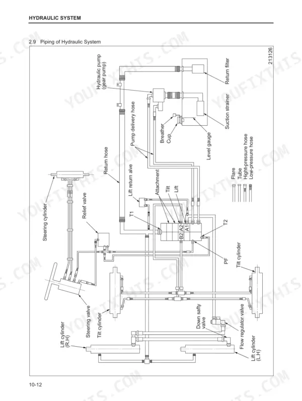
  • ✓ Hydraulic Schematics
  • ✓ Torque Specs
  • ✓ Multi-Level Bookmarks (2-level navigation)
Preview Sample Pages (PDF)
Add to Cart
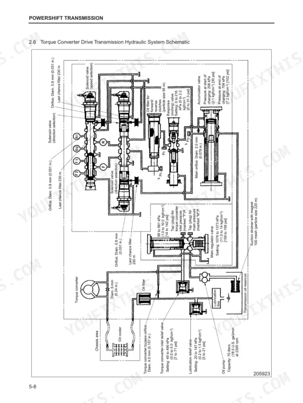
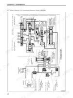
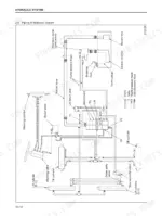
Mitsubishi FD70E powershift transmission hydraulic system schematic showing solenoid valves, oil filters, and pressure settings.
Mitsubishi FD70E Service Manual with Wiring Diagrams
$39.99

Instant Download 24/7

  • Works on PC, Mac, tablet, and phone.
  • Download once, keep forever


Guaranteed Safe Checkout
Visa Mastercard PayPal Apple Pay Google Pay

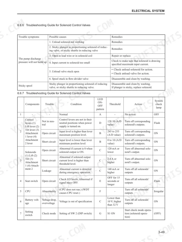
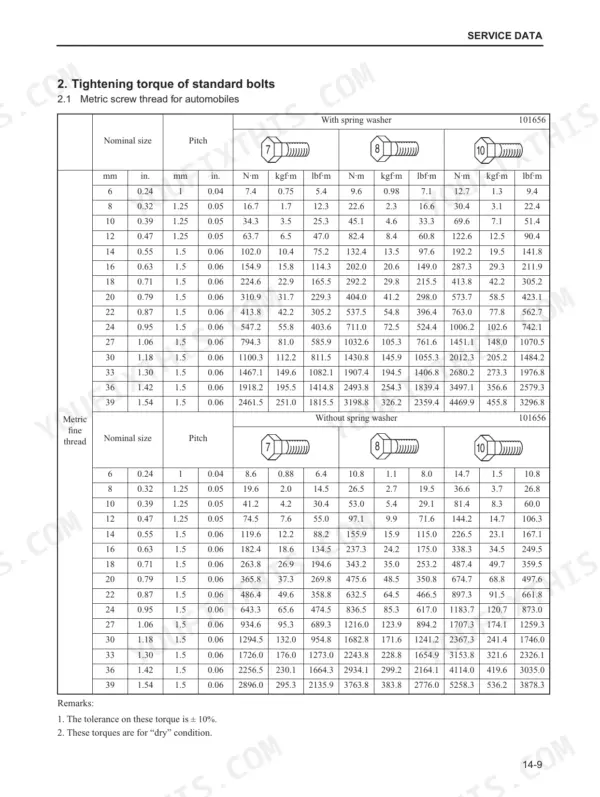
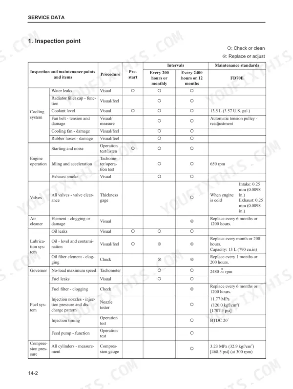
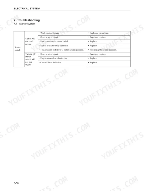
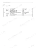
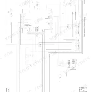
Cooling, electrical, powershift transmission, axles, brakes, steering, hydraulics, mast and attachments: the Mitsubishi FD70E service manual PDF (publication 99709-71100) covers each system on this forklift truck from start to finish over 397 pages. Hydraulic schematics trace oil from the pump and control valve out to the lift and tilt cylinders, and a wiring diagram maps the electrical circuits. Powershift transmission work fills one of the largest chapters in the book, with its own troubleshooting section. If a transmission solenoid acts up, the troubleshooting charts give you the cutoffs: 120 mA or lower means an open circuit, and 2.4 A or higher means a short. Fill the cooling system with 13.5 L (3.57 U.S. gal.) and set fan belt deflection to 12 mm (0.47 in.) under 98 N of force. A guessed mast bolt torque can drop a load. Chapter bookmarks and a searchable text layer take you straight to the standard bolt torque table in seconds.

What's Inside This Manual

SystemPagesKey Topics
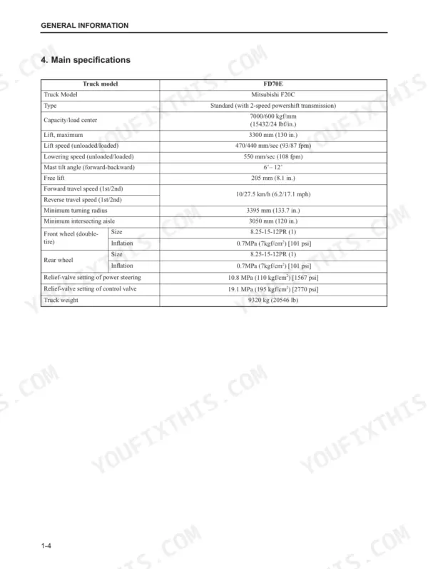
General Information1-16Model View, Truck Models Covered, Serial Number Locations, Main Specifications, Chassis and Mast Model Identification, Dimensions
Cooling System17-22Specifications, Structure, Inspection and Adjustment, Removing Fan Belt, Inspection of Fan Belt, Fan Belt Tension Adjustment
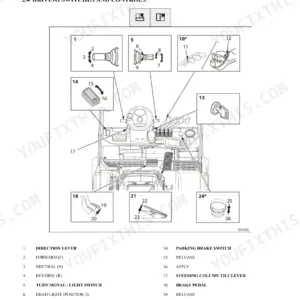
Electrical System23-77Major Components, Disassembly and Reassembly, Batteries and Charging, Location of Components, LC (Lever Control System), Electrical Wiring Diagram
Power Train78-92Specifications, Removal and Installation, Installation, Reduction Ratio, Removal and Installation of Engine and Transmission Unit, Draining Oil and Coolant, Removing Overhead Guard and Covers
Powershift Transmissions93-155Structure, Disassembly and Reassembly, Troubleshooting, Torque Converter, Control Valve, Main Regulator Valve, Torque Converter Drive Transmission Hydraulic System Schematic
Front Axle and Reduction Differential156-185Suggestions for Removal and Installation, Disassembly and Reassembly, Front Wheels (Tires)
Rear Axle186-205Removal and Installation, Disassembly and Reassembly, Troubleshooting, Power Cylinder, Rear Wheel (Tire)
Brake System206-240Disassembly and Reassembly, Adjustment and Testing, Troubleshooting, Wheel Brake, Brake Booster, Master Cylinder, Parking Brake
Steering System241-259Structure and Functions, Disassembly and Reassembly, Troubleshooting, Steering Hydraulic System, Steering Gear, Tilt Steering Assembly
Hydraulic System260-308Structure and Functions, Removal and Installation, Disassembly and Reassembly, Hydraulic Tank, Hydraulic Pump (Gear Pump), Control Valve, Lift Cylinder, Tilt Cylinder
Masts and Forks309-352Disassembly and Reassembly, Readjust, Troubleshooting, Simplex Mast, Triplex Mast, Operation of Triplex Mast
Fork Positioner353-365Suggestions for Removal and Installation, Disassembly and Reassembly, Troubleshooting, Applicable Attachment Models, Inspection and Repair
Side Shifter366-378Suggestions for Removal and Installation, Disassembly and Reassembly, Troubleshooting, Removing Forks, Removing Side Shifter Assembly, Installation
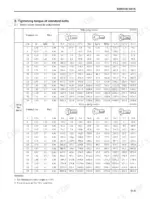
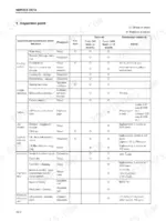
Service Data379-397Inspection Point, Tightening Torque of Standard Bolts, Periodic Replacement Parts

Quick Reference Specifications

SpecificationValuePage
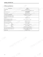
Clearance between cylinder body and piston0.020 to 0.105 mm (0.00079 to 0.00413 in.)p. 6
Total coolant capacity13.5 L (3.57 U.S. gal.)p. 18
Fan belt deflection12 mm (0.47 in.)p. 21
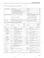
Solenoid open circuit threshold120 mA or lowerp. 71
Solenoid short circuit threshold2.4 A or higherp. 71
Tilt solenoid open circuit threshold120 mA or lowerp. 71
Tilt solenoid short circuit threshold2.4 A or higherp. 71
Free length of solenoid spring 187.5 mm (3.44 in.)p. 133
Free length of solenoid spring 1 (Repair or service limit)85 mm (3.35 in.)p. 133
Oil Pump Side clearance0.040 to 0.078 mm (0.0028 to 0.0043 in.)p. 148
Oil Pump Side clearance repair or service limit0.09 mm (0.0079 in.)p. 148
Wheel nut tightening torque382 ± 38 N•m (39 ± 3.9 kgf•m) [282 ± 28 lbf•ft]p. 160
BrandMitsubishi
ModelFD70E
Machine TypeForklift Truck
Manual TypeService Manual
LanguageEnglish
FormatSearchable PDF (Digital Download)
Pages397
File Size10 MB
Manual No.99709-71100
Serial RangeF20C-70001-up
Wiring DiagramsYes
Hydraulic SchematicsYes
Torque SpecificationsYes
Bookmarked / IndexedYes