
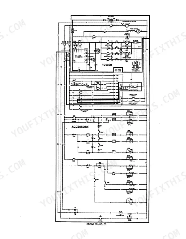
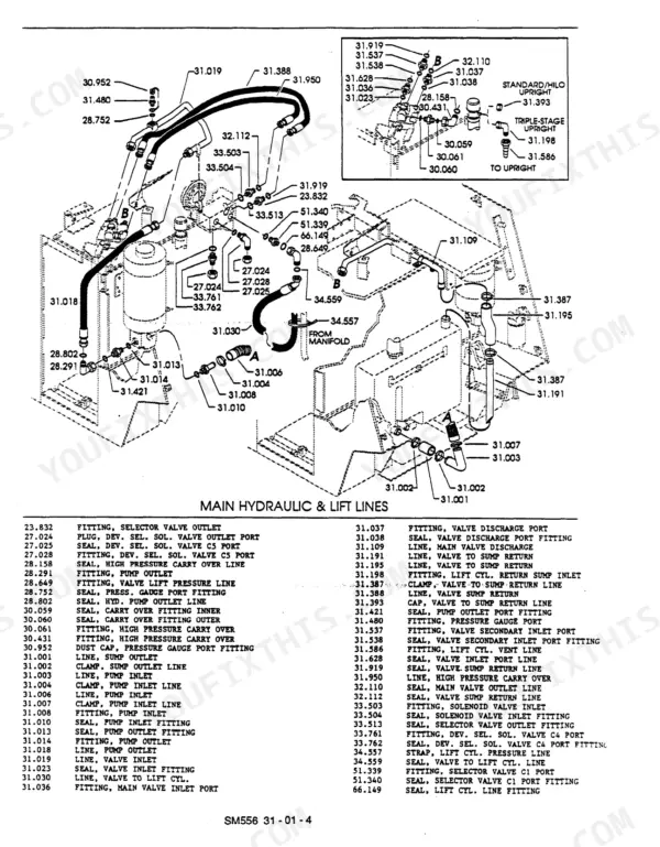
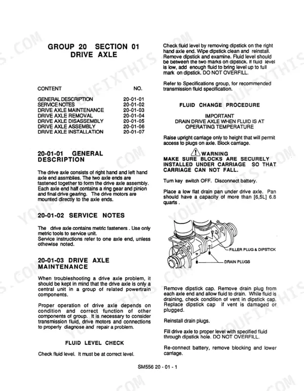

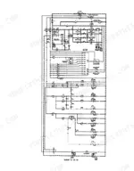
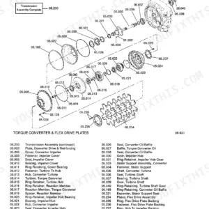
The Clark ESM 12 service manual PDF takes the ESM electric lift truck down system by system across 362 pages, covering seven variants of the series from the ESM 12 and 15S up to the ESM 25. Control panel operation and troubleshooting fills roughly a third of the book, walking you through the drive control sequence and hydraulic control circuit with error code tables and fault-finding charts for checking each component. Wiring diagrams trace the power and control wiring, and hydraulic schematics map the circuit from the main pump through the main valve, selector solenoid valve and tilt cylinders, with upright, carriage shim, brake and steer axle procedures behind them. A healthy thermal protector reads 50 to 200 ohms, and the rated figure to check a 36 volt battery against is 28.8 volts. One missing value can park a truck mid-shift. Bookmarks and a searchable text layer take you straight to that figure, so your lift truck goes back to moving pallets.
What's Inside This Clark ESM 12–25 Manual
| System | Pages | Key Topics |
|---|---|---|
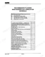
| How to Use This Manual | 4-8 | Group and Section, Component Specifications, Information Notes, Safety Messages, Index, Recommended Planned Maintenance and Lubrication Schedule, Safety Signs and Messages, Planned Maintenance Interval, Lubrication Schedule, Battery Maintenance, Drive Axle Fluid, Brake Adjustment, Upright Lubrication, Safety Signs, Notice, Caution, Warning, Danger |
| Planned Maintenance Program | 9-20 | Visual Inspection, Functional Tests |
| Battery Removal & Maintenance | 21-23 | Battery Removal and Handling, Battery Maintenance |
| Accelerator and Directional Control System | 24-28 | Accelerator and Directional Control Description, Control Handle Removal, Main Pump Motor Switch Check and Adjustment, Pump Motor Switch, Control Handle, Lift Switch, Lower Switch, Valve Spool Link |
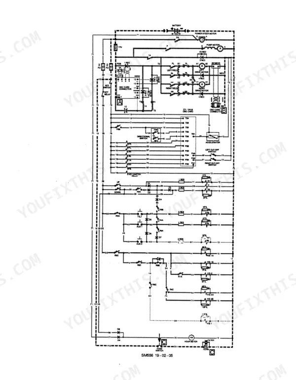
| Electrical System and Components | 29-32 | Brake Interlock Switch, Electrical Assemblies, Control Wiring, Power Wiring, Battery Discharge Indicator |
| Electric Motor General Maintenance | 33-52 | Inspection Procedures, Brush and Commutator Inspection, Drive Motor, Main Pump Motor, Steer Pump Motor, Motor Description, Drive Motor Installation, Main Pump Motor Description, Main Pump Motor Inspection, Steer Pump Motor Description, Steer Pump Motor Removal, Steer Pump Motor Disassembly |
| Drive Motor Overhaul | 53-63 | Brush Removal and Inspection, Motor Disassembly, Motor Reconditioning, Drive Motor Cut-Out Switch Check and Adjust, Cut-Out Switch, Steering Tiller Arm, Cut-Out Cam, RH Switch, LH Switch |
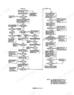
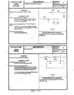
| Control Panel | 64-205 | Control Panel Description, Control Panel Troubleshooting, Control Panel Removal, Control Panel Operation and Troubleshooting, Operation Sequence Drive Control, Hydraulic Control Circuit, Checking Components |
| Drive Axle | 206-214 | Drive Axle Maintenance, Drive Axle Removal, Drive Axle Disassembly |
| Cushion Wheels and Tires | 215-231 | Cushion Drive Tire Removal, Steer Wheel Removal, Pneumatic Drive Tire and Wheel Maintenance, Pneumatic Drive Tire Specifications, Pneumatic Drive Wheel and Tire Removal |
| Hydraulic Brake System | 232-234 | Brake System Description, Brake Bleeding Procedure |
| Brake Master Cylinder | 235-253 | Master Cylinder Operation, Master Cylinder Disassembly, Brake Slave Cylinder, Service Brake, Slave Cylinder Operation, Slave Cylinder Disassembly, Brake Operation, Knott Brake Inspection and Adjustment, Brake Shoe Replacement |
| Steering Gear | 254-275 | Steering Gear Description, Steering Gear Troubleshooting, Steering Axle, Power Steering Pump, Steer Torque Generator, Steering Axle Removal, Steering Pump Description, Steer Torque Generator Description, Steer Torque Generator Disassembly |
| Main Hydraulic Pump | 276-303 | Pump Description, Main Hydraulic Valve, Hydraulic System, Tilt Cylinder, Selector Solenoid Valve, Main Valve Description, Main Valve Troubleshooting, General Description, Hydraulic Sump Tank, Tilt Cylinder Removal, Tilt Cylinder Adjustment, Selector Valve Description |
| Upright | 304-331 | Upright Maintenance, Carriage Shim Inspection |
| Upright Removal | 332-335 | Truck Preparation |
| Counterweight | 336-339 | Counterweight Maintenance, Counterweight Installation |
| Machine Jacking & Blocking | 340-346 | Raising Drive Wheels, Blocking the Upright, Overhead Guard, Sheet Metal and Trim, Truck Data Plate and Decals, Overhead Guard Maintenance, Instrument Panel, Front Cover, Top Hood, Hydraulic Valve Cover, Side Pad, Floor Plate, Capacity Plate, Serial Number Plate, Warning Decal, Electrical Cleaning Instruction, Battery Specification Decal, Fork Safety Decal |
| Truck Data and Specifications | 347-353 | Power Supply Battery, Torque Chart |
| Hydraulic and Electric Diagrams | 354-362 | Hydraulic Diagram, Electrical Schematic, Electrical Diagram |
Quick Reference Specifications
| Specification | Value | Page |
|---|---|---|
| Control handle lever clamping screw torque | 23-31 lbf-ft (2.5-3.5 Nm) | p. 27 |
| Control handle horizontal clamping screw torque | 15-20 lbf-ft (1.6-2.3 Nm) | p. 27 |
| 24 volt battery rated voltage | 19.2 volts | p. 125 |
| 36 volt battery rated voltage | 28.8 volts | p. 125 |
| Thermal protector resistance | 50 to 200 ohms | p. 135 |
| 1A Time adjustment | 1.5 SEC. | p. 137 |
| Axle shaft fastener torque | 40 - 45 N·m (30 - 33 lbf·ft) | p. 219 |
| Cylinder tube torque | 40.7 N·m (30 lbf·ft) | p. 274 |
| Pump body gear contact surface wear depth limit | 0.012 mm (0.005 in.) | p. 280 |
| Pump shaft seal installation depth | 6 mm (1/4 inch) | p. 280 |
| Drain pan capacity for hydraulic oil | 13.5 L (3.5 gallon) | p. 289 |
| 1A Contactor Coil Resistance | 19.55 ohms | p. 348 |
Clark ESM 12–25 Common Problems This Manual Covers
Clark ESM 12-25 lift truck accelerator and directional control handle binds, operates off center, and does not return to center
Remove the control handle following the procedure starting on page 24 and inspect the lever, ball joint and switch contacts for binding or wear. On reassembly, torque the lever clamping screw to 2.5-3.5 Nm, then hold the control lever horizontal and torque the horizontal clamping screw to 1.6-2.3 Nm as listed on page 27.
Manual Section: Accelerator and Directional Control System p. 24Accelerator potentiometer shows lack of speed control between creep speed and top speed positions
Measure the accelerator potentiometer with an ohmmeter following the check on page 195. With the accelerator in the creep speed position you should read 4800 to 6000 ohms; at top speed it should read 50 ohms or less. A reading outside either range points to the potentiometer or its wiring, so trace that before condemning the control card.
Manual Section: Control Panel Operation and Troubleshooting p. 195Control panel 1A, forward, reverse, or pump contactor coil suspected open or failing to pull in
Inspect the contactors using the control panel procedures starting on page 64. Measure each coil with an ohmmeter and compare against the data on page 348: the 1A and forward/reverse coils should read 19.55 ohms, the pump contactor coil 20 ohms. Replace any coil that reads open or out of spec before you suspect the panel itself.
Manual Section: Control Panel p. 64Power steering pump relief valve pressure low or out of adjustment on the steering circuit
Test the power steering relief pressure with a gauge and compare it to the 1000 psi setting listed on page 349. If it reads off, adjust the relief valve following the power steering pump procedure starting on page 264. If pressure is on spec, move to the steering gear troubleshooting on page 254 and work through it there.
Manual Section: Power Steering Pump p. 264Upright cylinder drifts down when the forks are raised and left holding a load
Check the upright cylinder for drift following the cylinder troubleshooting in the Upright section starting on page 304. If the cylinder is leaking past its seals, repair it and install new seals per the same section. If the cylinder checks good, run the main hydraulic valve troubleshooting starting on page 283 before you tear anything else down.
Manual Section: Upright p. 304Main hydraulic pump body worn on the low pressure inlet side gear contact surface
Remove and disassemble the main hydraulic pump, then measure wear on the inlet side gear contact surface; replace the body assembly if wear exceeds 0.012 mm (0.005 in.) per page 280. Press the new shaft seal 6 mm (1/4 inch) below the pilot face, torque cover fasteners to 28-32 lbf-ft, and torque mounting capscrews to 48-54 lbf-ft following page 282.
Manual Section: Main Hydraulic Pump p. 280Frequently Asked Questions
How do you clear a Clark ESM fault code?
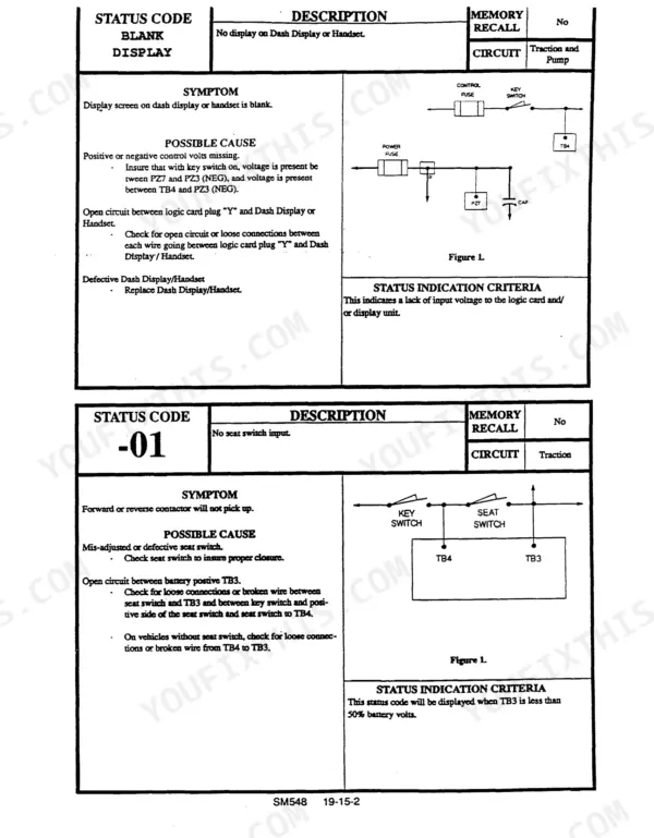
To clear a fault code, you must first identify the cause of the fault. For many fault codes, such as the PMT type fault, the system can be reset by cycling the key switch. For other specific status codes, the fault code will be overwritten each time a new fault occurs, or it can be cleared from memory by adjusting the function value to zero using the Handset tool. p. 153
Why will a Clark ESM electric forklift not move or lift?
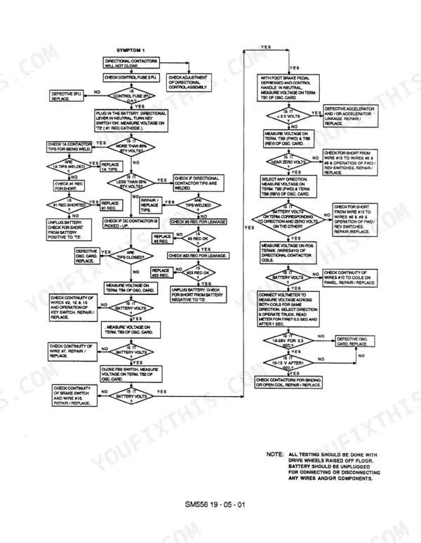
If the forklift will not move or lift, check for fault codes on the Handset or dash display. For example, if the directional contactors will not close, check the control fuse 2FU, the directional control assembly, or for welded contactor tips. Refer to the Symptom Chart on page 82 and the specific troubleshooting flow charts starting on page 144 for detailed diagnostic steps. p. 144
What is the recommended torque for the drive axle to frame mounting bolts on a Clark ESM 12-25 lift truck?
The recommended tightening torque for the drive axle to frame mounting bolts is 301 - 339 lbf-ft (408 - 469 N-m). p. 352
How often should the lift chains be inspected and lubricated?
The lift chains should be inspected and lubricated every truck Planned Maintenance (PM) interval, which is every 50-250 hours. If the truck is operating in corrosive environments, the chains should be inspected every 50 hours. p. 319
What is the correct brake fluid to use for the hydraulic brake system?
The hydraulic brake system requires SAE J1703b DOT 3 brake fluid. p. 234
What do I get after purchasing this Clark ESM 12 manual?
You get a 362-page searchable PDF that downloads instantly after checkout. Open it on your laptop, tablet, or phone, and bring it right to the shop floor.
Can I print pages of this Clark ESM 12 manual for my own shop?
You can. Print the sections you want for your own use and keep the file as your backup.

Reviews
There are no reviews yet.