

Part of the Case Repair Manuals.
Steering pressure checks, transmission stall diagnosis, and mast service on Case's G Series forklifts get settled by one document: the Case 586G, 588G repair manual PDF, OEM 87728464, putting 691 pages of factory procedure behind both models. A complete schematic set closes out the book, tracing hydraulic circuits and electrical wiring so you can follow a dead solenoid or a lazy lift circuit back to its source. Power train coverage takes up roughly a third of the total, walking the standard transmission, drive axle, and planetaries from pressure check through teardown and reassembly. Torque two wheel drive steering cylinder mounting screws to 335 Nm (247 lb-ft), then seat the rear wheels at 156 to 203 Nm. Mast drift under load ruins your whole week. This bookmarked, text searchable PDF is bought once; download it and it stays yours for the life of the truck.
Other edition of this manual
What's Inside This Case 586G, 588G Repair Manual
| System | Pages | Key Topics |
|---|---|---|
| General | 3-19 | Section Index - General (Standard Torque Specifications, Fluids and Lubricants, Metric Conversion Chart) |
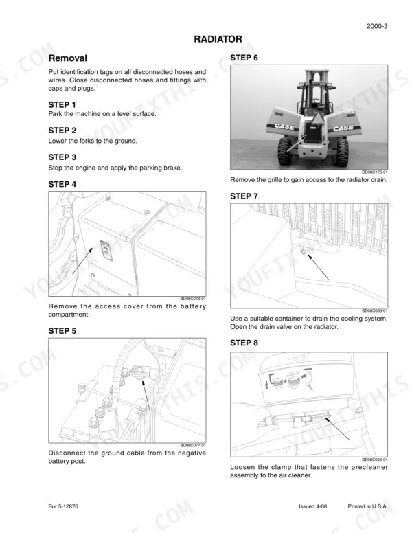
| Engine | 20-70 | Section Index - Engine (Engine and Radiator Removal and Installation, Stall Test, Diagnosing Engine Oil Consumption, Engine Balancer, Turbocharger Diagnosis Procedure Family 3 Engines) |
| Fuel System | 71-85 | Section Index - Fuel System (in Vehicle Injector Pump Removal and Installation) |
| Electrical | 86-174 | Section Index - Electrical (Removal and Installation of Electrical Components, Electrical Specifications and Troubleshooting, Batteries, Starter and Starter Solenoid) |
| Steering | 175-289 | Removal and Installation of Steering Components, Steering Specifications, Pressure Checks and Troubleshooting, Steering Control Valve, Steering Cylinders |
| Power Train | 290-538 | Removal and Installation of Power Train Components, Standard Transmission Specifications, Pressure Checks, And Troubleshooting, Wheels and Tires, Drive Axle and Planetaries |
| Brakes | 539-557 | Section Index - Brakes (Removal and Installation of Brake Components, Hydraulic Brake Troubleshooting, Master Cylinder) |
| Hydraulics | 558-654 | Removal and Installation of Hydraulic Components, Hydraulic Specifications, Troubleshooting, And Pressure Checks, Cleaning the Hydraulic System, Hydraulic Pump, Control Valve |
| Mounted Equipment | 655-689 | Section Index - Mounted Equipment (Pedals and Levers, ROPS Canopy, Seat and Seat Belt, Forklift Mast) |
| Schematic Set | 690-691 | Hydraulic and Electrical Schematics |
Quick Reference Specifications
| Specification | Value | Page |
|---|---|---|
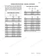
| 37 Degree Flare Fitting Torque (1/4 inch Tube OD) | 72 to 144 Pound-Inches (8 to 16 Newton metres) | p. 8 |
| 37 Degree Flare Fitting Torque (5/16 inch Tube OD) | 96 to 192 Pound-Inches (11 to 22 Newton metres) | p. 8 |
| Four wheel drive steering cylinder mounting screws | 120 Nm (89 lb-ft) | p. 223 |
| Two wheel drive steering cylinder mounting screws | 335 Nm (247 lb-ft) | p. 223 |
| Rear wheel, two wheel drive torque | 156 to 203 Nm (115 to 150 pound-feet) | p. 335 |
| Rear wheel, four wheel drive torque | 251 Nm (185 pound-feet) | p. 335 |
| Allen head bolts for retainer in brake housing torque | 25 Nm (221 pound-inches) | p. 339 |
| Allen head bolts for carrier and brake housing to center section torque | 79 Nm (58 pound-feet) | p. 339 |
| Pinion nut rotating torque (without seal) | 1.6 to 2.4 Nm (14.2 to 21.1 pound-inches) | p. 339 |
| Differential bearing preload rotating torque (without seal) | 1.9 to 2.8 Nm (16.9 to 24.9 pound-inches) | p. 339 |
| Allen head screws for shifter assembly | 23 Nm (204 pound-inches) | p. 413 |
| Clutch disc clearance | 2.3 to 4.3 mm (0.09 to 0.17 inch) | p. 462 |
Case 586G, 588G Common Problems This Manual Covers
Case 586G steering wheel hard to turn, hydraulic fluid leaking at steering cylinder rod end
Check for constant leakage at the open fitting with the cylinder pressurized; steady flow means damaged piston packing. Replace the packing with a new seal kit, then reinstall the cylinder and torque the mounting screws to 120 Nm (89 lb-ft) on four wheel drive machines, per the chart on page 223.
Manual Section: Steering p. 223Power shuttle slips or engages harshly when shifting between forward and reverse
Verify transmission clutch pressures before teardown. If pressures check good, pull the clutch pack and measure disc clearance; replace discs when clearance falls outside 2.3 to 4.3 mm (0.09 to 0.17 inch), the spec on page 462. Air test the assembled pack at 620 kPa (90 psi) to confirm the piston seals hold.
Manual Section: Power Train p. 462Mast lifts slowly under load and drifts down with the engine off
Test the main relief valve first; the setting on page 585 is 214 to 235 bar (3100 to 3400 psi). If relief pressure checks good, run a pump output test at full throttle. Low flow at pressure means a worn pump; if flow is good, replace the lift cylinder piston seals and inspect the rod for scoring.
Manual Section: Hydraulic System Troubleshooting p. 585Brake pedal feels spongy and machine pulls to one side when braking
Bleed both brake circuits, then tighten each air bleeder screw to 12 Nm (108 pound-inches) as specified on page 550. Test the left and right circuits separately with a gauge; uneven pressure between sides points to a failing master cylinder. Check push rod to piston clearance, which must measure 0.025 to 0.050 inch (0.6 to 1.3 mm).
Manual Section: Hydraulic Brake Troubleshooting p. 550Whining or rumbling noise from the drive axle that changes with ground speed
Drain the axle oil and check for metal flake. Remove the differential and inspect the pinion and carrier bearings for spalling. On reassembly, set pinion bearing preload to 1.6 to 2.4 Nm rotating torque and ring gear backlash to 0.20 to 0.28 mm (0.008 to 0.010 inch), both specs listed on page 339.
Manual Section: Power Train p. 339Frequently Asked Questions
What are the torque specifications for the front wheel mounting nuts on a Case 586G/588G forklift?
The front wheel mounting nuts must be tightened to a final torque of 305 Nm (225 pound-feet). After reaching this torque, turn each nut an additional 30 degrees to set the required pre-load. p. 335
What is the procedure for checking the piston packing for the steering cylinder?
To check the piston packing, disconnect the hose at the left side of the steering cylinder and install a plug. Start the engine, run at full throttle, and turn the steering wheel all the way to the right while holding it there. If there is constant leakage from the open port, the piston packing is damaged and must be repaired as per Section 5003. p. 205
What is the capacity of the hydraulic system for the 586G/588G forklift?
The total hydraulic system capacity is 68.1 liters (72 U.S. quarts). The capacity with a filter change is 54.9 liters (58 U.S. quarts), and the capacity without a filter change is 53.0 liters (56 U.S. quarts). p. 12
What is the correct torque for the cap screws that fasten the steering cylinder to the four wheel drive steering axle on a Case 586G, 588G forklift?
The cap screws that fasten the steering cylinder to the four-wheel drive steering axle must be tightened to 162 to 178 Nm (119 to 131 pound-feet). p. 178
What is the procedure for bleeding air from the brake system?
To bleed the brake system, install a clear plastic hose with a 1/4 inch I.D. onto the brake bleeders and insert the other end into a drain pan. Start the engine at low idle, open a bleeder valve, and watch for air-free oil. Once air-free, close the valve and repeat for the other bleeder. Finally, push the brake pedal down to 63.5 mm (2.5 inches) and release the parking brake to clear air from the crossover tube. p. 545
What exactly do I receive with this Case 586G Repair Manual?
You get a 691-page searchable PDF that downloads instantly after checkout. Open it on your laptop, tablet, or phone, and bring it right to the shop floor.
Am I free to print this Case 586G Repair Manual?
Yes. Print the pages or sections you need for your own shop use. Any standard printer works.









Reviews
There are no reviews yet.