
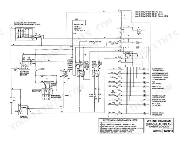
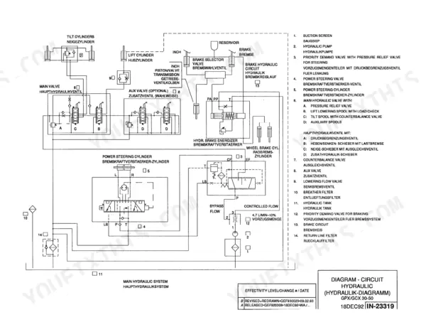
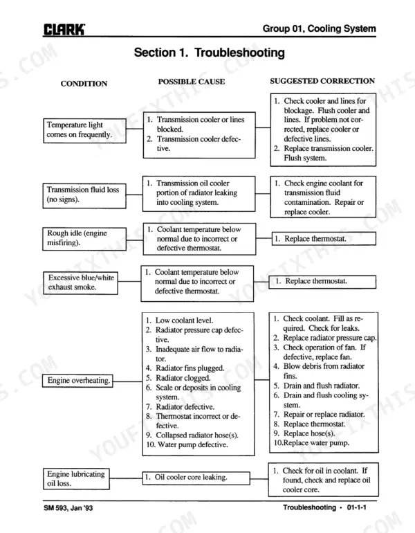
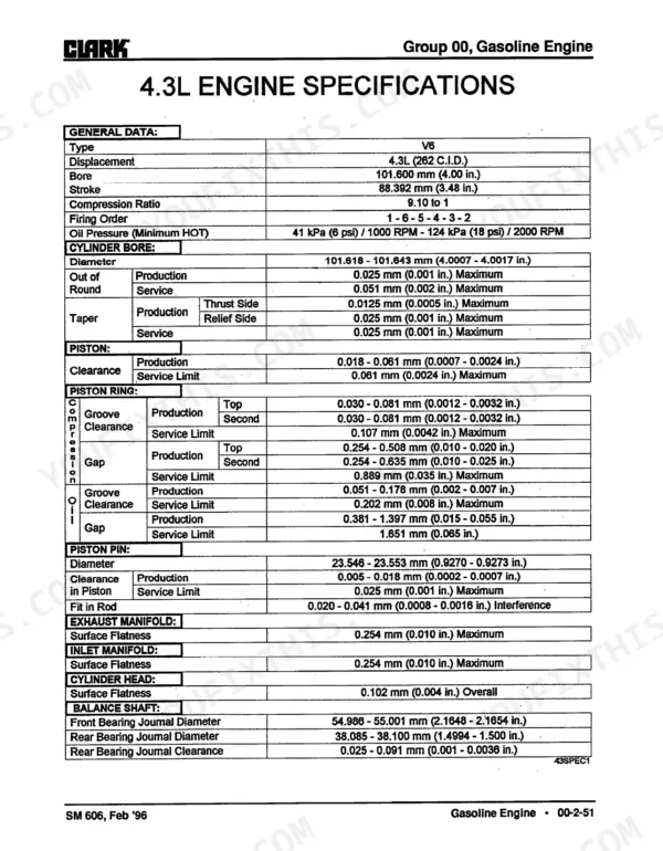
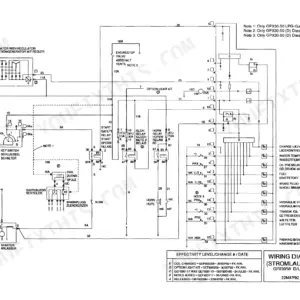
Rebuilding a Clark GPX 35, 40 or 50E forklift without calling the dealer is the job this 411-page service manual PDF is built for, running from engine removal through uprights and counterweights. The electrical chapter pairs a wiring color code with wiring diagrams, while the lift circuit section ends on a hydraulic schematic tracing oil from the sump and pump through the control valve to the lift and tilt cylinders. Transmission overhaul fills one of the thickest chapters in the book, and troubleshooting charts for cooling, brakes, steering and uprights help you narrow a fault before anything comes apart. Keep LPG fuel lines at least 2 in. (50,8 mm) clear of exhaust parts, and torque connecting rod nuts to 27 N·m (20 lb. ft.) plus a 70° turn. A mast that creeps under load can eat a shift. With bookmarked chapters and a text layer you can search, you confirm the exact component and your nameplate data before ordering parts.
What's Inside This Clark GPX 35/40/50E Manual
| System | Pages | Key Topics |
|---|---|---|
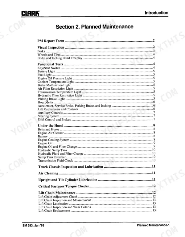
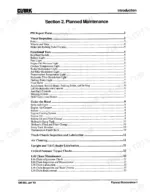
| Introduction | 6-23 | Safety, Planned Maintenance |
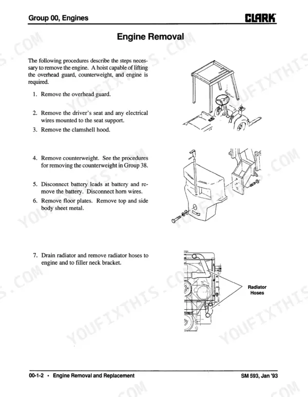
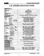
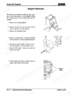
| Engines | 24-91 | Engine Removal, Diesel Workshop Manual, Gas/LPG Workshop Manual |
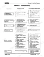
| Cooling System | 92-101 | Troubleshooting, Cooling System Testing and Maintenance, Fan Belt Replacement, Radiator Removal |
| Fuel System | 102-129 | Fuel Pump Pressure Test, IMPCO Fuel System, Carburetor Overhaul, Velocity Governor Overhaul, Removal of IMPCO Vaporizing System |
| Transmission | 130-181 | Transmission Checks, Transmission Drain and Refill, Transmission Removal, Transmission Overhaul |
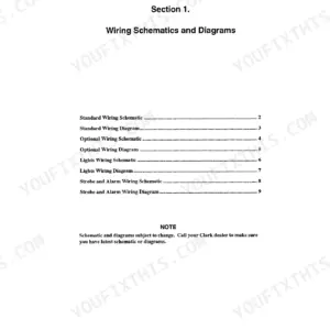
| Electrical System | 182-197 | Wiring Color Code, Wiring Diagrams, Electrical Checks |
| Drive Axle | 198-220 | Axle End Lubrication, Axle End Removal, Axle Ends Overhaul, Differential Overhaul |
| Wheels and Tires | 221-232 | Lifting, Jacking, And Blocking, Wheels and Tires Mounting |
| Braking/Inching System | 233-257 | System Description/Troubleshooting, Brake and Inching System Bleeding, Brake and Inching Pedals Adjustment, Master Cylinder Overhaul, Power Booster Overhaul, Brake Caliper Overhaul |
| Steering Column and Gear | 258-282 | Troubleshooting, Steering Column and Gear Removal, Char-Lynn Steering Control Unit |
| Steer Axle | 283-304 | Steer Axle Removal, Steer Axle Overhaul, Steering System Adjustment, Steer Cylinder Removal, Steer Axle Wheel Bearings, Steer Cylinder Overhaul |
| Hydraulic Sump, Filters, and Pump | 305-313 | Hydraulic Sump and Filters, Hydraulic Pump Troubleshooting and Overhaul |
| Hydraulic Valve/Lift Circuit | 314-328 | Hydraulic System Pressure Check, Hydraulic Valve Overhaul, Hydraulic Valves, Hydraulic Schematic |
| Tilt Cylinders | 329-337 | Tilt Cylinder Removal, Tilt Cylinder Overhaul, Tilt Lock Valve |
| Uprights | 338-381 | Troubleshooting and Visual Inspection, Operational Checks, Carriage Check and Adjustment, Upright Check and Adjustment, Cylinder Repair, Lift Chain Maintenance |
| Counterweights | 382-385 | Counterweight Removal and Reinstallation |
| Specifications | 386-411 | Nameplates/Decals, PM Inspection and Drivers Daily Inspection Forms, Recommended Lubricants & Lubricant Specifications, Lubrication Intervals |
Quick Reference Specifications
| Specification | Value | Page |
|---|---|---|
| Balance Gear Driven Gear Bolt | 20 N·m (15 lb. ft.) plus a 35° turn | p. 88 |
| Connecting Rod Bolt Nuts | 27 N·m (20 lb. ft.) plus a 70° turn | p. 88 |
| Fuel line clearance from exhaust system parts | 2 in. (50,8 mm) | p. 111 |
| Hydrostatic relief valve pressure setting | 400 psi (2758 kPa) | p. 111 |
| Hydraulic Sump Drain/Refill Interval | Every 2000 hours or once a year | p. 411 |
| Valve assembly fastener torque | 83-93 N.m (61-69 lbf-ft) | p. 322 |
| Gland nut torque | 102-142 N.m (75-105 lbf-ft) | p. 335 |
| Drift limit | 7/8 inch in a minute | p. 367 |
| Gland cap torque | 50-60 lbf-ft (67-81 N·m) | p. 368 |
| Main Pump (Vane Type) Flow | 105.0 L/min. (27.74 GPM) @ 17237 kPa (2500 PSI) @ 2600 RPM | p. 396 |
| Engine Oil Capacity (with filter) | 5 Quarts | p. 394 |
| Engine Oil Capacity (without filter) | 4 Quarts | p. 394 |
Clark GPX 35/40/50E Common Problems This Manual Covers
Clark GPX 35, 40, 50E forklift upright will not lift the load and lift speeds are sluggish
Check the hydraulic sump fluid level first, then work through the upright troubleshooting and visual inspection steps starting on page 338. Run the operational checks for lift and tilt, then verify carriage adjustment, upright adjustment and lift chain condition before you pull any hydraulic components.
Manual Section: Uprights p. 338Upright will not hold the load and drifts down, failing the drift test
Run the upright drift test and time the fall. If the upright drops more than 7/8 inch in a minute, follow the cylinder repair on page 367. Check load holding at the hydraulic valve as well, and torque the gland cap to 50-60 lbf-ft (67-81 N·m) on reassembly.
Manual Section: Uprights p. 367Main hydraulic pump shows low flow, foam in oil, and fails to build pressure
Check sump fluid level and look for foam before touching the pump. Test flow against 105.0 L/min (27.74 GPM) at 2500 PSI and 2600 RPM at operating temperature, per page 396. If the oil is foamy or overdue for service, drain and refill the sump and replace suction line, return line, and breather filters following page 411.
Manual Section: Hydraulic Sump, Filters, and Pump p. 305Hydraulic valve spools not returning to neutral, jerky motion, oil leaks at the valve
Check hydraulic system pressure and relief valve action using the pressure check procedure in the section starting on page 314. Inspect each spool for sticking and verify detent action. On reassembly, torque valve assembly fasteners to 61-69 lbf-ft (83-93 N·m) per page 322, and torque valve mounting bolts to 59-64 lbf-ft (80-87 N·m).
Manual Section: Hydraulic Valve/Lift Circuit p. 314Service brake pedal drops to the floor or feels spongy, insufficient stopping power
Check the brake reservoir level and inspect the master cylinder and calipers for leaks. Bleed the brake and inching system following the section starting on page 233, then adjust the brake and inching pedals. If the pedal still sinks, overhaul the master cylinder or power booster.
Manual Section: Braking/Inching System p. 233Engine overheating and temperature warning light coming on during normal forklift operation
Check fan belt deflection first: 0.25-0.50 inch (6.5-12.5 mm) in the long span at 50-80 lb, per page 393. Test the radiator cap against its 7.0 psi relief pressure and verify the thermostat opens at 182° F (83°C). Work through the troubleshooting steps on page 93 for remaining causes.
Manual Section: Cooling System p. 93Frequently Asked Questions
What are the torque specifications for the engine mounting bolts on the GPX 30/50E?
The engine mounting bolts for the GPX 30/50E should be torqued to 164-184 N-m (121-136 lbf-ft). p. 396
What is the correct procedure for checking the lift chain tension?
Place a load on the forks and raise them slightly. When under load, push the chains forward and pull them backward; the tension should be equal on both sides. If one chain moves more than the other, lower the load and adjust the chain anchor bolt for equal tension. p. 345
How often should I drain and refill the transmission on a Clark GPX 35/40/50E forklift?
The transmission, convertor, and axle adaptor have a common sump that should be drained and refilled every 1000 hours. p. 138
What is the correct cylinder head bolt torque for the 4.3L V6 engine in the Clark GPX 35/40/50E forklift?
The cylinder head bolts must be tightened in three steps: first to 34 N-m (25 lbs. ft.), second to 61 N-m (45 lbs. ft.), and finally to 90 N-m (65 lbs. ft.). p. 81
What is the specified fan belt deflection for the cooling system?
The fan belt should be adjusted to a deflection of 6.5-12.5 mm (0.25-0.50 inch) in the long span at 222-356 N (50 lb-80 lb) at the center of the alternator-crank-shaft pulley. p. 393
What exactly do I receive with this Clark GPX 35 Service Manual?
A 411-page Service Manual in searchable PDF format, available the moment you complete checkout. View on computer, tablet, or phone, with no shipping wait.
Can I print just the pages I need from this Clark GPX 35 manual?
Yes. Print a single page or a chapter for your own shop use, on letter or A4.



Reviews
There are no reviews yet.