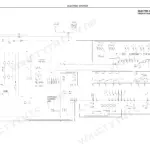
An hour from now you could be checking boom slide pad wear on your telescoping forklift against factory limits, working from this 382-page Lull 1044C-54 service manual PDF (OEM ID 31200079), which also covers the Series II. The mid-inlet hydraulic schematic traces every circuit from pump through control valve, while the electrical schematic maps the wiring behind the shift logic and proximity switches. Removal, installation, and overhaul procedures work through the four-section boom, transfer carriage, frame tilt, transmission, axles, and outriggers, backed by troubleshooting charts for pump and transmission faults. Set the boom extension proximity switch gap at 0.19 to 0.25 inch, then torque the new transmission filter to 20-25 lb-ft (27-34 Nm) at the 50-hour first change. A guessed pressure figure costs a seal, or a hand. Bookmarked and keyword-searchable, with exploded views that show exactly which piece you're ordering before you call the parts counter.
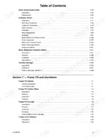
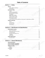
What's Inside This Lull 1044C-54 Manual
| System | Pages | Key Topics |
|---|
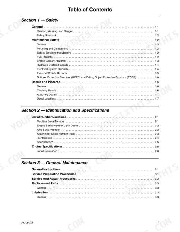
| Safety | 23-34 | General (Caution, Warning, And Danger, Safety Standard) |
| Identification and Specifications | 35-44 | Serial Number Locations (Machine Serial Number, Engine Serial Number, John Deere, Axle Serial Number, Attachment Serial Number Plate), Identification, Specifications |
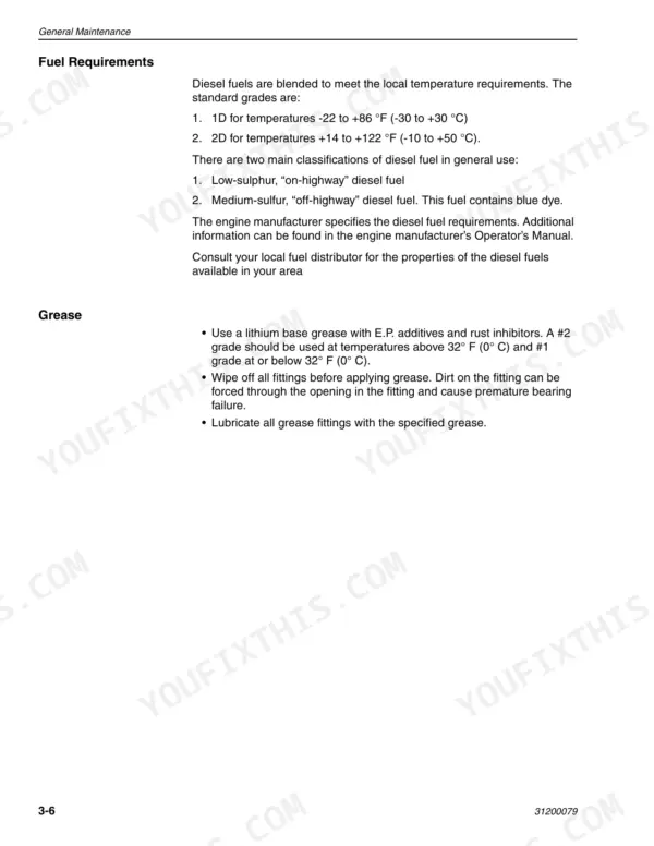
| General Maintenance | 45-66 | Service Preparation Procedures, Service and Repair Procedures, Replacement Parts (General), Lubrication (General) |
| Reference Diagrams | 67-82 | Mid-Inlet Hydraulic Schematic, Control Valve, Electrical Schematic |
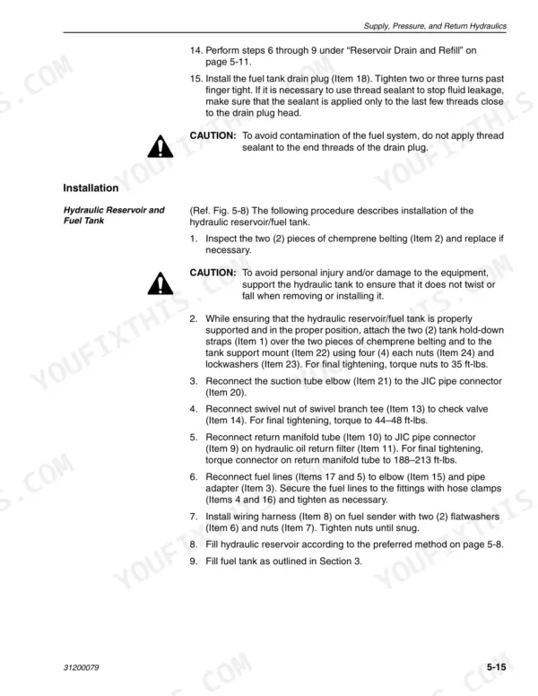
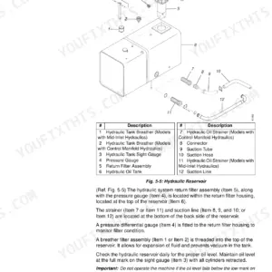
| Supply, Pressure, and Return Hydraulics | 83-142 | General (Major System Components, Hydraulic Systems, Safe Maintenance Practices, Cleanliness, Checking Hydraulic Lines) |
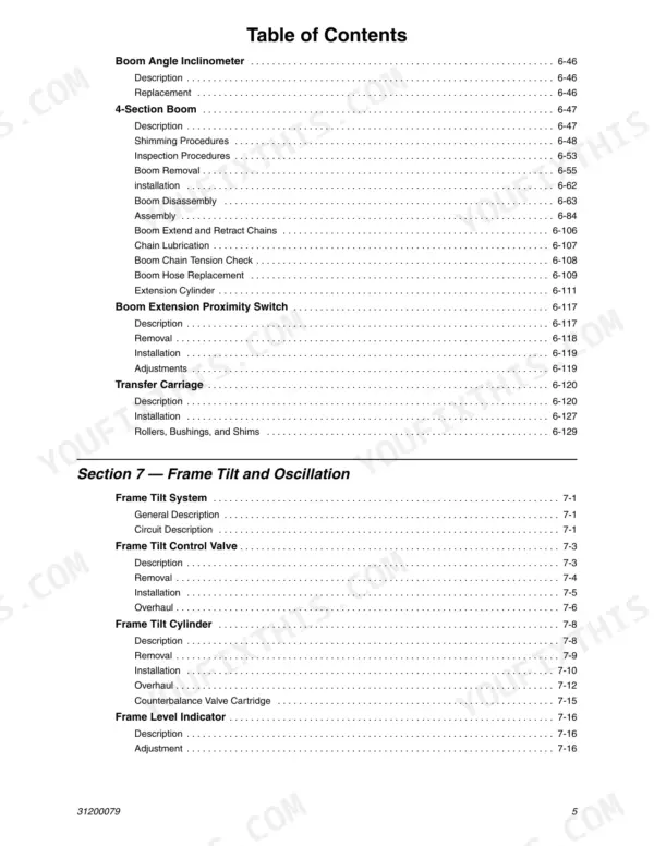
| Boom and Transfer | 143-282 | Boom and Transfer Hydraulics, Joystick Controls (Removal, Installation, Disassembly), Hydraulic Cylinders (Description, Checking Cylinder Condition) |
| Frame Tilt and Oscillation | 283-324 | Frame Tilt System (Circuit Description), Frame Tilt Control Valve (Description, Removal, Installation, Overhaul) |
| Transmission | 325-344 | Transmission Assembly Component Terminology, Transmission Description, Transmission Operation |
| Axles and Brakes | 345-364 | Axle and Drive Shaft Component Terminology (Axle Assembly), Axle Inspection, Internal Service and Repair, Axle Installation (Axle Service and Troubleshooting) |
| Outriggers | 365-382 | General, Removal, Installation |
Quick Reference Specifications
| Specification | Value | Page |
|---|
| Boom extension proximity switch gap | 0.19 inch to 0.25 inch | p. 261 |
| Boom elevation proximity switch gap | 0.19 in to 0.25 in | p. 321 |
| Transmission oil and filter change interval | 1,000 hour | p. 329 |
| Transmission filter change interval (first) | 50 hours | p. 329 |
| Transmission fuse rating | 7.5 amp | p. 338 |
| Lift and Carry Capacity | 10,000 lbs. | p. 39 |
| Maximum Lift Height | 54 Feet | p. 39 |
| Hydraulic System Capacity | 65 Gallons | p. 39 |
| Fuel Tank Capacity | 36 Gallons | p. 39 |
| Transmission Drain and Refill Capacity | 19 Quarts | p. 39 |
| Boom Hoist and Extend Valve Relief Pressure | 3000 psi | p. 40 |
| Steering System Pressure | 2355 psi | p. 40 |