
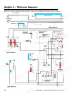
A boom that drifts under load or a frame that won't hold level often traces back to a valve or cylinder nobody can pin down without factory data. That data sits in this 636-page Lull 644B service manual PDF (OEM ID 10709790), which covers six forklift variants across the 644B, 844C, 1044C and K-series family. Hydraulic schematics for the control manifold and mid-inlet systems trace flow through the pump unloader valve, rear oscillation lock and boom extend lockout circuits, with ZF DW-2 and DW-3 harness diagrams right behind them. Boom and transfer work takes up the biggest share of the book, from shimming to full teardown of 2, 3 and 4-section booms. Transmission control pressure should read 230 to 260 psi on your gauge, and the return filter flange nuts take 35 ft-lbs. One missing torque value can park a machine all day. Bookmarked and text-searchable, your copy pairs exploded views with each rebuild so you order the right component the first time.
What's Inside This Lull 644B, 844C, 1044C Manual
| System | Pages | Key Topics |
|---|---|---|
| Safety | 27-38 | General (Caution, Warning, And Danger, Safety Standard), Maintenance Safety, Decals and Placards |
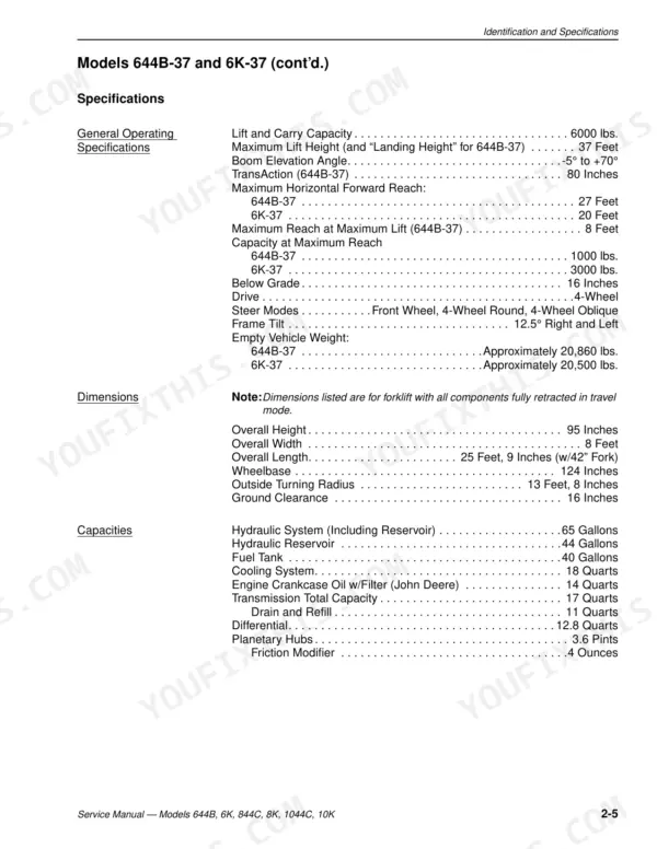
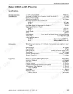
| Identification and Specifications | 39-66 | Serial Number Locations, Engine Specifications |
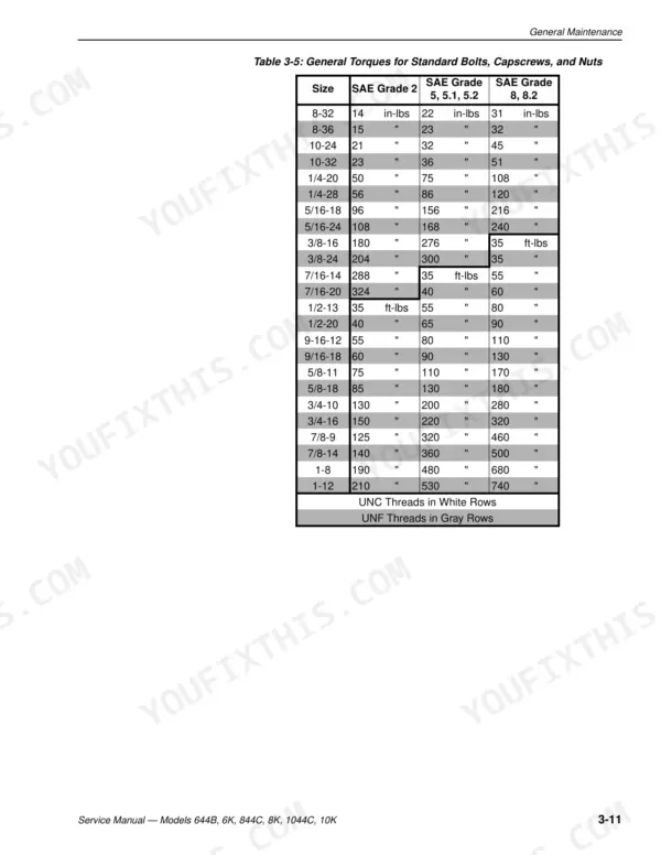
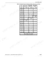
| General Maintenance | 67-87 | Service Preparation Procedures, Service and Repair Procedures, Replacement Parts (General), Lubrication (General), Torque Specifications |
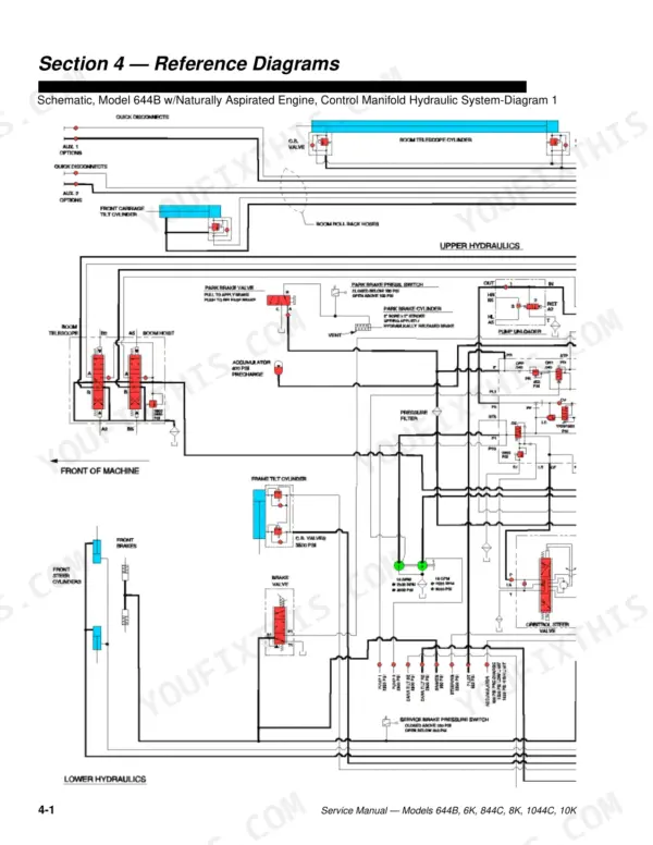
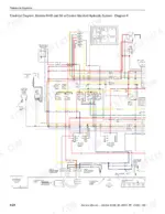
| Reference Diagrams | 88-140 | Schematic, Model 644B W/ Naturally Aspirated Engine, Control Manifold Hydraulic System, Mid-Inlet Hydraulic System |
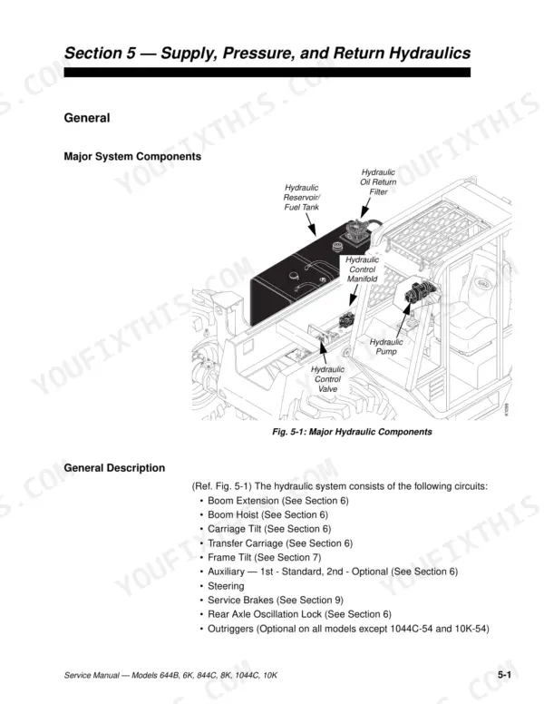
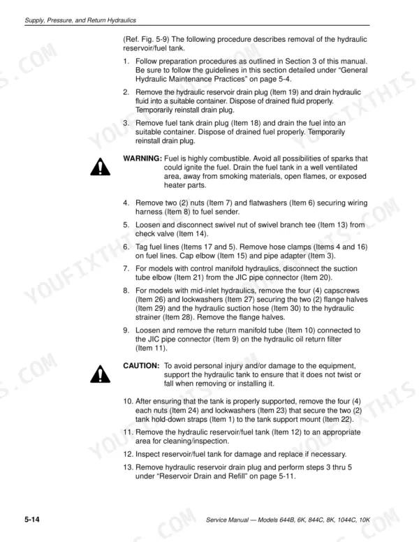
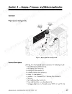
| Supply, Pressure, and Return Hydraulics | 141-240 | Hydraulic Reservoir, Hydraulic Pump, Multi-Spool Control Valve, Hydraulic Control Manifold, Pump Unloader Valve |
| Boom and Transfer | 241-310 | Boom and Transfer Hydraulics, Joystick Controls (Removal, Installation, Disassembly), Hydraulic Cylinders (Description, Checking Cylinder Condition), Joystick Controls, Hydraulic Cylinders, Boom Hoist Cylinder, Carriage Tilt Cylinder, Selector Valve |
| Section Boom | 311-339 | Shimming Procedures, Inspection Procedures, Extension Cylinder |
| Section Boom | 340-395 | Shimming Procedures, Inspection Procedures, Extension Cylinder |
| Section Boom | 396-463 | Shimming Procedures, Inspection Procedures, Boom Removal, Boom Disassembly, Extension Cylinder |
| Extension Proximity Switch and Transfer Carriage | 464-498 | Transfer Carriage, Boom Cradle, Transfer Cylinder |
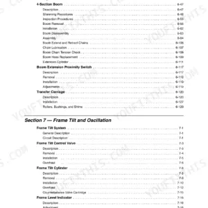
| Frame Tilt and Oscillation | 499-547 | Frame Tilt System, Frame Tilt Control Valve, Frame Tilt Cylinder, Frame Level Indicator, Rear Oscillation Lock System, Rear Oscillation Lock Cylinder, Oscillation Control Block, Frame Tilt Lockout Valve |
| Transmission | 548-572 | ZF Transmission, Dw-2 Shifter, Dw-3 Shifter, Troubleshooting, Electrical System |
| Brakes | 573-616 | Service Brakes, Service Brake Pedal and Valve, Accumulator, Park Brake |
| Outriggers | 617-636 | Outrigger Cylinders, Differential Pressure Switch, Boom Extension Proximity Switch, Outrigger Control Valves |
Quick Reference Specifications
| Specification | Value | Page |
|---|---|---|
| General Torque for Standard Bolts (SAE Grade 2, 8-32) | 14 in-lbs | p. 79 |
| Transmission control pressure | 230–260 psi (16–18 bar) | p. 553 |
| Compensator Valve Cartridge (CS Port) Torque | 65 ft-lbs. | p. 219 |
| Suction tube elbow torque | 250–283 ft-lbs | p. 165 |
| Hydraulic suction hose capscrews torque | 55 ft-lbs | p. 165 |
| Joystick connector torque | 25–29 ft-lbs | p. 254 |
| Joystick capscrew torque | 50 in-lbs | p. 254 |
| Torque swivel nuts on hoses | 50–58 ft-lbs | p. 435 |
| Torque swivel nuts on hydraulic tubes | 50–58 ft-lbs | p. 435 |
| Transmission valve solenoid resistance | 24–40 W | p. 552 |
| Frame Tilt Angle | 12.5° Right and Left | p. 45 |
| Hydraulic Reservoir Capacity | 44 Gallons | p. 45 |
Lull 644B, 844C, 1044C Common Problems This Manual Covers
Boom chain rollers and lower chain showing excessive chain wear during extend and retract
Inspect the chain roller pins and lower chain, then reinstall the roller lock pin with thread locking compound and torque the capscrew to 55 ft-lbs on page 373. Adjust the lower chain and torque the adjustment capscrew to 75 in-lbs following page 384. Check your serial number before setting upper chain nuts.
Manual Section: Boom and Transfer p. 373Boom joystick controls giving jerky boom functions with pilot pressure out of specification
Measure joystick pilot pressure and compare it against 460 ±25 psi on page 258. If the joystick is at fault, remove and disassemble it, torque the ported guide to 260 in-lbs per page 256, and reinstall on the control panel with capscrews at 50 in-lbs following page 254.
Manual Section: Boom and Transfer p. 258ZF transmission not responding to shifter signals or showing low transmission pressure
Verify electrical supply to the transmission first, then check shifter signals and test each transmission valve solenoid following page 552. Test short and long harness continuity and the inductive transmitter. Measure transmission pressure against 230 to 260 psi (16 to 18 bar) as listed on page 553.
Manual Section: ZF Transmission Troubleshooting p. 552Frequently Asked Questions
What are the torque specifications for the wheel lug nuts on the Lull 644B, 6K, 844C, 8K, 1044C, and 10K models?
The wheel lug nuts for these models should be torqued to 320 ft-lbs. p. 46
How do you fix lull 644B 844C 1044C hydraulic pump excessive noise, overheating, or system not developing pressure?
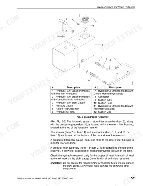
Check reservoir level and look for loss of fluid first. Inspect the suction hose flange at the hydraulic oil strainer and torque the capscrews to 55 ft-lbs, with the suction tube elbow at 250 to 283 ft-lbs, following page 165. Verify the main relief valve is torqued to 20 ft-lbs as shown on page 207. p. 141
How do you fix hydraulic return filter pressure reading above the acceptable operating range at the reservoir?
Measure return filter pressure and compare it against the 0 to 15 psi range on page 167. Replace the filter element if it reads high, then press the cover down, rotate it under the flange nuts, and torque them to 35 ft-lbs per page 169. p. 167
How do you fix boom slide pads showing excessive wear with jerky boom extend and retract functions?
Inspect the front and rear slide pads on each boom section and replace worn pads, reinstalling the upper and side shims. Torque the pad retainer capscrews to 200 ft-lbs and the side pad button head capscrews to 65 ft-lbs following page 371. Use page 372 for the inner and middle boom rear pads. p. 371
Is this Lull 644B manual a download or a disc?
All 636 pages arrive as one searchable PDF at checkout. Read it at the desk, then take the phone out to the machine.
Am I able to print pages from this Lull 644B manual?
Printing is allowed without restriction. Pull the pages you need for the job and bin them when they get greasy.
Is the electrical system covered in this Lull 644B Service Manual?
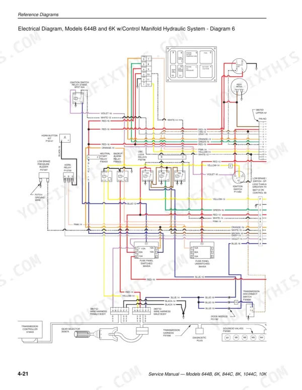
Yes. The Reference Diagrams section includes electrical diagrams for the 644B and 6K with the control manifold hydraulic system and for the ZF DW-2/EST-19 and DW-3 system harnesses. Page 108 carries the first of them.



Reviews
There are no reviews yet.