
Clark put its own name on this 445-page factory service manual PDF for the ESM-II electric lift truck family, covering seven variants from the ESM-II 12 through 25. Nearly a third of the book belongs to electrical controls, where EV-100MK troubleshooting and recommended tests sit beside wiring schematics that trace each circuit from the control handle switches to the drive, pump, and steer motors. Hydraulic schematics back up the lift and steering circuit pressure checks, while your drive axle, brake, steering gear, and upright chain jobs each run from removal to installation. Set plugging distance to roughly 6.7 m (22 ft), then confirm the right drive wheel stops once the steering axle trunnion swings 41.5° off center. A contactor rebuild stalls on one number, and it's 1.6-2.0 N·m. Bookmarks and a text layer handle the screen side, but you can also print a chapter and let it take the grease at the bench.
What's Inside This Clark ESM-II 12 thru 25 Manual
| System | Pages | Key Topics |
|---|---|---|
| Planned Maintenance | 9-26 | Maintenance Schedules, Planned Maintenance Procedures |
| Safe Maintenance | 27-35 | Safety, Lifting, Jacking, And Blocking |
| Battery | 36-44 | Battery Handling |
| Electrical Control Handle | 45-51 | Control Handle Switches |
| Electrical Motors | 52-92 | General Information, Drive Motors, Hydraulic Pump Motor, Steer Pump Motor |
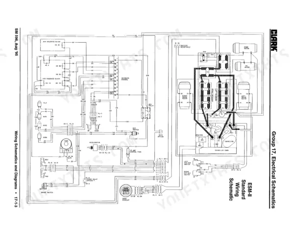
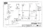
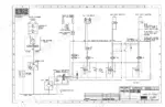
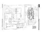
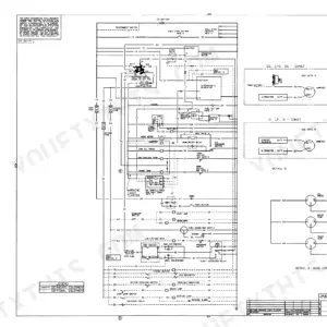
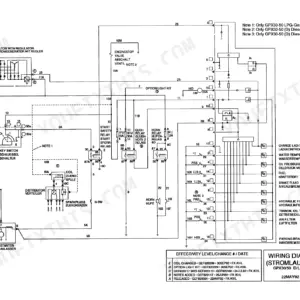
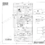
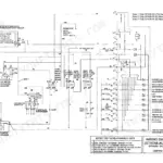
| Electrical Schematics | 93-102 | Wiring Schematics and Diagrams |
| Electrical Controls | 103-235 | Control Panel, Ev-100MK Troubleshooting, Recommended Tests, Equipment, And Procedures, Drive Axle Cut-Out Switch Check and Adjustment, Forward and Reverse Switches |
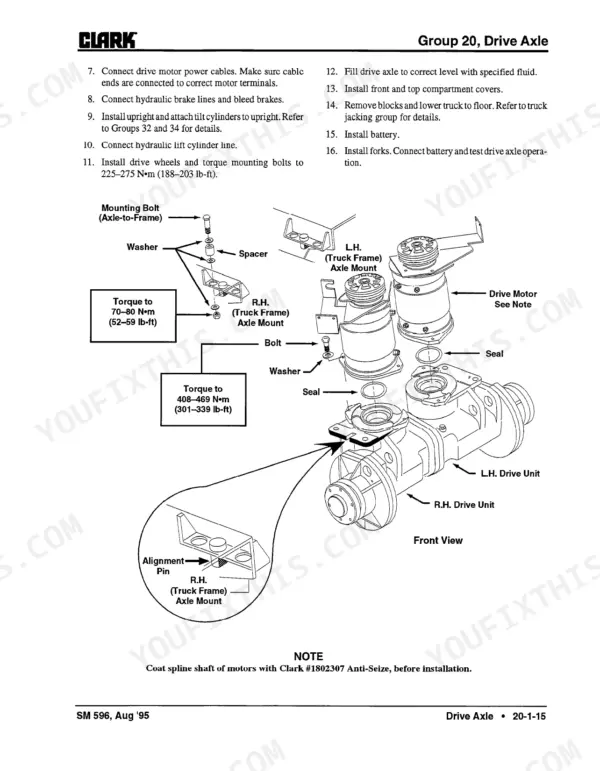
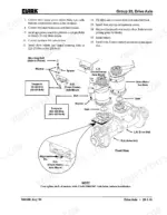
| Drive Axle | 236-251 | Drive Axle Maintenance, Drive Axle Removal, Drive Axle Disassembly, Drive Axle Assembly, Drive Axle Installation |
| Wheels and Tires | 252-270 | Cushion Wheels and Tires, Pneumatic Drive Tire and Wheel Maintenance |
| Brake System | 271-284 | Brake System and Bleeding, Brake Adjustment, Brake Slave Cylinder |
| Steering Gear | 285-294 | Steering Gear Description, Steering Gear Troubleshooting, Steering Gear Removal, Steering Gear Disassembly, Steering Gear Assembly, Steering Gear Installation |
| Steering Axle | 295-320 | Steering Axle Repair, Power Steering Pump, Steer Torque Generator |
| Hydraulic Pump, Sump and Filters | 321-331 | Hydraulic Pump, Hydraulic Sump and Filter |
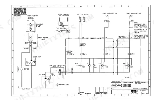
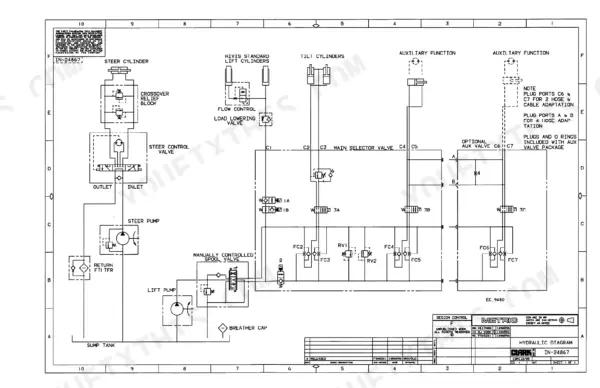
| Hydraulic Control Valves | 332-362 | Main Control Valve, Face Seal Fittings, Hydraulic System Pressure Checks - Lift Circuit, Hydraulic System Pressure Checks - Steering Circuit |
| Hydraulic Supply System | 363-368 | Hydraulic System |
| Cylinders | 369-382 | Tilt Cylinder |
| Selector Solenoid Valve | 383-387 | Selector Solenoid Valve Description, Selector Solenoid Valve Troubleshooting, Selector Solenoid Valve Removal, Selector Solenoid Valve Repair, Selector Solenoid Valve Installation |
| Upright | 388-424 | Chain Inspection, Adjustment, And Replacement |
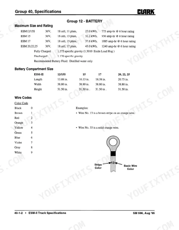
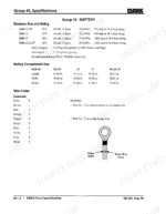
| Specifications | 425-445 | Esm-II Truck Specifications, Esm-II Truck Data Plate, Lubricants and Shop Supplies |
Quick Reference Specifications
| Specification | Value | Page |
|---|---|---|
| All Models | ||
| Fixed contact set bolt torque | 1.6-2.0 N·m (14-18 lb-in.) | p. 116 |
| Armature and movable contact assembly retaining nut torque | 1.6-2.0 N·m (14-18 lb-in.) | p. 116 |
| BDI Lockout battery state of charge threshold | 10% | p. 197 |
| Pinion gear backlash | 0.102-0.198 mm (0.0040-0.0078 in) | p. 250 |
| Flange cap screws torque | 67 N·m (49.5 lb-ft) | p. 250 |
| Power Steering Time Delay | 24 seconds | p. 429 |
| Drive Motor Mounting Bolt Torque | 70-80 N·m (52-59 lb-ft) | p. 63 |
| Drive Axle Mounting Bolt Torque | 408-469 N·m (301-339 lb-ft) | p. 250 |
| Steering Gear Mounting Capscrew Torque | 34-38 N·m (25-28 lb-ft) | p. 294 |
| Hydraulic Pump Mounting Capscrew Torque | 65-73 N·m (48-54 lb-ft) | p. 327 |
| ESM-II 12-17 | ||
| Tilt Cylinder Relief Pressure (ESM-II 12-17) | 13,780 kPa (2000 psi) | p. 357 |
| ESM-II 20-25 | ||
| Tilt Cylinder Relief Pressure (ESM-II 20-25) | 15,857 kPa (2300 psi) | p. 357 |
Clark ESM-II 12 thru 25 Common Problems This Manual Covers
Clark ESM-II lift truck displays status code -07 or -08 with accelerator input voltage at TB1 out of range
Measure input voltage at TB1 first. For code -07 it should read less than 3.7 volts (page 202); for code -08 it should read more than 3.0 volts (page 203). During the card check, replace the card if voltage is not greater than 4.5 volts. Verify TB1 to battery negative resistance is greater than 4.7K ohms.
Manual Section: Electrical Controls p. 202BDI lockout active and truck stops operating as battery state of charge drops
Check battery state of charge before you start chasing controller faults. The BDI lockout described on page 197 stops operation when the battery state of charge reaches 10%. Charge the battery following the battery handling procedures on page 36, then retest the truck. If operation still stops, move on to the status code checks.
Manual Section: Electrical Controls p. 197Solenoid control card indicator lights show hydraulic functions or lift function disabled
Check the indicator lights on the solenoid control card first, because they tell you where to start. Work through the Solenoid Control Card Troubleshooting steps for the exact condition shown, and treat a lift function disabled fault separately from all hydraulic functions disabled. Verify wiring against the electrical schematics on page 94 before condemning the card.
Manual Section: Solenoid Control Card TroubleshootingDrive axle cut-out switch fails to stop right drive wheel on a sharp turn
Check the drive axle cut-out switch with the drive wheels raised and safely blocked (page 33). Turn the steering axle trunnion and verify the right drive wheel stops turning at 41.5° from the center, straight-ahead position, per page 152. Adjust the switch until the wheel stops at that angle, then repeat the check.
Manual Section: Electrical Controls p. 152Tiller arm spins freely or shows high steering effort, kickback, and slow response
Check the steering gear against the troubleshooting chart for each symptom, starting with whether the tiller arm spins freely or kicks back. If the gear comes out for repair, follow the removal, disassembly and assembly steps, then torque the steering gear mounting capscrews to 34-38 N·m (25-28 lb-ft) as shown on page 294.
Manual Section: Steering Gear p. 285Upright chains showing elongation, edge wear, turned pins, cracked plates or tight joints
Inspect each chain along its full length for elongation, edge wear, turned or protruding pins, cracked plates and tight joints. Follow the Chain Inspection, Adjustment, and Replacement procedures in the Upright section, which starts on page 388. Replace any chain that fails inspection, then adjust it using the same procedure.
Manual Section: Upright p. 388Frequently Asked Questions
What do the error codes on the Clark ESM-II display mean?
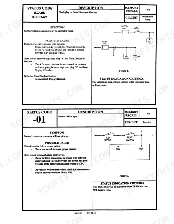
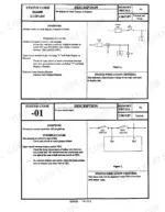
The status codes on the digital readout indicate specific faults. For example, code -01 indicates a 'No seat switch input', while code -06 indicates 'Accelerator depressed with no direction selected'. Other codes like -02, -03, -04, and -05 relate to directional switch or accelerator faults. Any code other than those listed in the fault codes table indicates the truck needs service and you should call a service technician. p. 19
How do I reset the controller on a Clark ESM-II?
To reset the controller after certain faults, you must return the directional selection lever to the neutral position. If either the brake switch or key switch is opened, the control will shut off and cannot be restarted until the directional lever is returned to the neutral position. p. 108
What is the torque specification for the drive axle mounting bolts on the Clark ESM-II 12 thru 25?
The drive axle mounting bolts must be torqued to 408–469 N·m (301–339 lb-ft). p. 250
What is the correct torque for the drive motor mounting bolts on a Clark ESM-II 12 thru 25?
The drive motor mounting bolts and washers should be torqued to 70–80 N·m (52–59 lb-ft). p. 63
What is the procedure for bleeding the brake system?
To bleed the brake system, attach a pressure bleeder to the bleeder screw on the slave cylinder. Open the bleeder screw to allow fluid under low pressure to push air out of the system and into the reservoir. Continue until no air bubbles appear in the fluid, then close the bleeder screw and disconnect the pressure bleeder. Repeat this procedure at the opposite slave cylinder and adjust the fluid level in the reservoir. p. 274
Is this Clark ESM-II 12 manual a PDF I download?
All 445 pages arrive as one searchable PDF at checkout. Read it at the desk, then take the phone out to the machine.
Can I print this Clark ESM-II 12 manual?
Yes. Many buyers print one chapter at a time for their own shop and keep the rest on a tablet.

Reviews
There are no reviews yet.