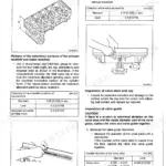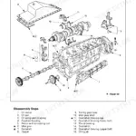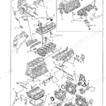
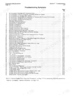

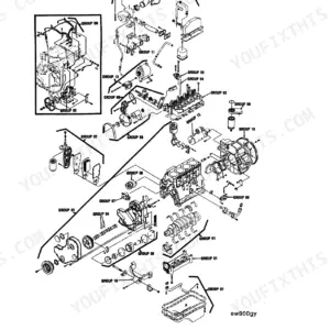
This is the Cummins Troubleshooting and Repair Manual for the L10 diesel engine, factory publication 3810246-03, supplied as a 619 page PDF download. It covers the engine itself, whatever your L10 happens to power, from dataplate identification and symptom based troubleshooting charts through full system repair and base engine overhaul.
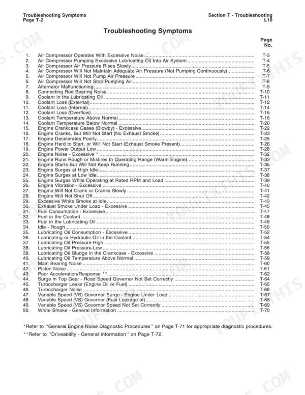
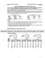
The manual is organized by system: cooling, lubricating oil, combustion air, compressed air, fuel, electrical, and base engine components, followed by engine testing, removal and installation, and a component specifications section with capscrew markings and torque values. The troubleshooting section alone runs from a symptoms list through cause and correction charts, including air compressor and coolant diagnosis.
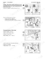
If the engine is apart on the stand, this is where the numbers live: connecting rod capscrews torqued in three steps to 210 N·m [155 ft-lb] then loosened and repeated (page 427), cylinder liner clamping at 45, 95 and 140 N·m (page 438), turbocharger axial and radial clearances. Download it, print the pages you need, and put the L10 back together to spec.
What's Inside This Cummins L10 Manual
| System | Pages | Key Topics |
|---|---|---|
| Introduction | 3-13 | About the Manual, Symbols Used in This Manual, General Repair Instructions |
| Engine Identification | 14-20 | Engine Dataplate, Engine Specifications, Engine Diagrams |
| Troubleshooting | 21-92 | Troubleshooting Symptoms, Air Compressor Troubleshooting, Coolant Troubleshooting |
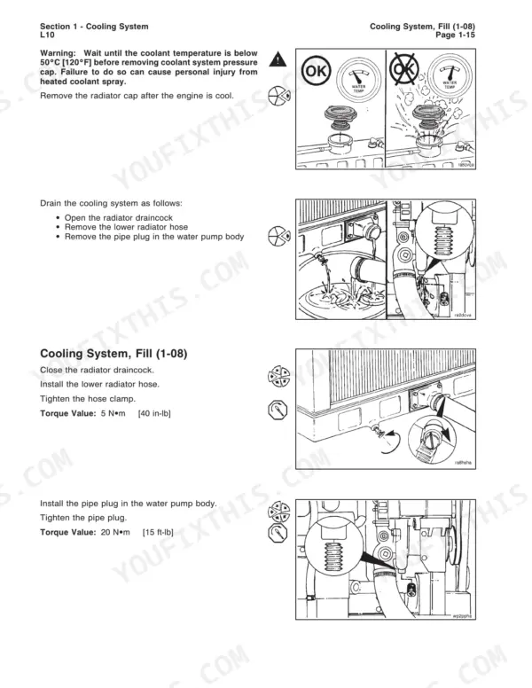
| Cooling System | 93-181 | Coolant Filter, Thermostat, Radiator, Fan Clutch, Cooling System Diagnostic Procedure |
| Lubricating Oil System | 182-216 | Oil Pressure Gauge, Oil Filter, Oil Pan, Oil Cooler, Oil Pump |
| Combustion Air System | 217-235 | Turbocharger, Intake Air Restriction, Exhaust Air Restriction, Air Leaks |
| Compressed Air System | 236-257 | Air Compressor, Air Governor, Unloader Valve, Cylinder Head |
| Fuel System | 258-353 | Fuel Pump, Fuel Filter, Injectors, Pace System, Fuel Line Restriction |
| Electrical System | 354-368 | Batteries, Starting Circuit, Alternator, Starting Motor |
| Base Engine Components | 369-553 | Cam Followers, Camshaft, Connecting Rods, Cylinder Head, Flywheel, Vibration Damper |
| Engine Testing | 554-565 | Engine Testing Service Tools, General Engine Test Procedures, Chassis Dynamometer Operation |
| Engine - Remove and Install | 566-573 | Engine Remove and Install Service Tools, General Information |
| Engine Component Specifications | 574-603 | Base Engine Component Specifications, Capscrew Markings and Torque Values, Decimal and Metric Equivalents |
| Additional Service Literature | 609-614 | Additional Service Literature Listing, Service Literature Ordering Locations, Service Publications Order Form |
| Accessory Component Manufacturers | 615-619 | Component Manufacturers Page 1, Component Manufacturers Page 2, Component Manufacturers Page 3 |
Quick Reference Specifications
| Specification | Value | Page |
|---|---|---|
| Cylinder head capscrew torque Step 1 | 100 N·m [75 ft-lb] | p. 405 |
| Cylinder head capscrew torque Step 2 | 170 N·m [125 ft-lb] | p. 405 |
| Cylinder head water test fixture nut torque | 45 N·m [35 ft-lb] | p. 407 |
| Fuel Pump Throttle Lever Breakover | 3.18 mm to 6.35 mm (0.125 in to 0.250 in) | p. 591 |
| Water Pump Impeller Bore I.D. | 15.339 mm to 15.365 mm (0.6039 in to 0.6049 in) | p. 585 |
| Water Pump Shaft O.D. at Impeller | 15.389 mm to 15.402 mm (0.6058 in to 0.6064 in) | p. 585 |
| Oil Pump Drive Shaft End Clearance | 0.064 mm to 0.207 mm (0.0025 in to 0.0106 in) | p. 586 |
| Injector Preload (Top Stop Injector) | 0.6 Nm to 0.7 Nm (5 in-lb to 6 in-lb) | p. 596 |
| Turbocharger Compressor Impeller Radial Clearance | 0.15 mm to 0.41 mm (0.006 in to 0.016 in) | p. 588 |
| Turbocharger Turbine Wheel Radial Clearance | 0.27 mm to 0.47 mm (0.011 in to 0.019 in) | p. 588 |
| Engine Dry Weight | 876 kg | p. 16 |
| Oil Pressure (Low Idle) | 70 kPa | p. 17 |