
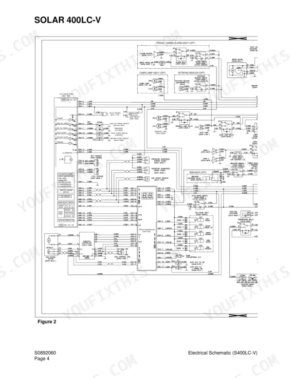
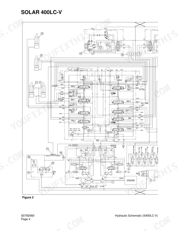
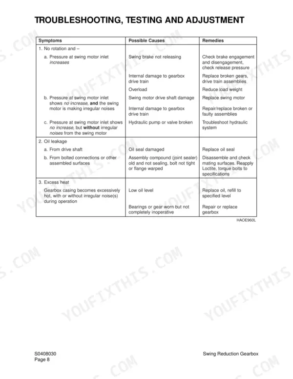
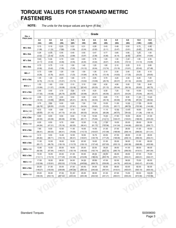
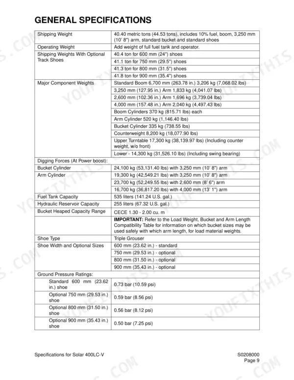
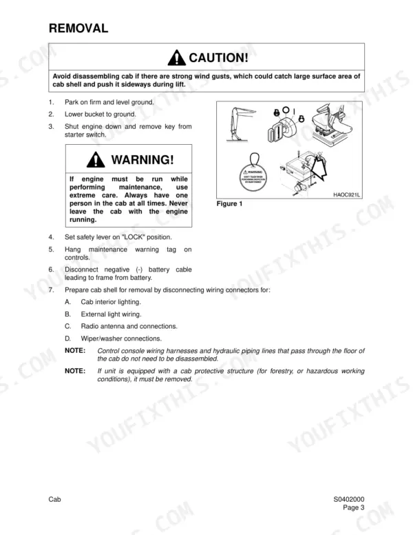
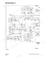
Looking for a Daewoo Solar 400LC-V shop manual PDF straight from the factory? This 612-page shop manual (OEM #2023-7140AE) walks you through the whole hydraulic excavator, from swing bearing, swing reduction gearbox, and track assembly to the main pump with regulator. You get full hydraulic schematics plus troubleshooting, testing, and adjustment procedures for the main control valve, swing motor, and travel motor, along with complete electrical schematics for chasing wiring faults. A standard torque section and page after page of teardown procedures handle the cab, counterweight, fuel tank, center joint, cylinders, and boom and arm. Fit standard 600 mm track shoes or the optional 750 mm, and torque 1/2-inch split flanges to 15-18 ft lbs, 3/4-inch to 22-27. No more diagnosing pressure drops from forum threads. Bookmarked and keyword-searchable; pull it up on any device and get wrenching.
What's Inside This Daewoo Solar 400LC-V Manual
| System | Pages | Key Topics |
|---|---|---|
| Safety | 7-30 | Track Excavator Safety S0102000 |
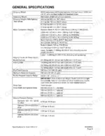
| Specifications | 31-52 | Specifications for Solar 400LC-V S0208000 |
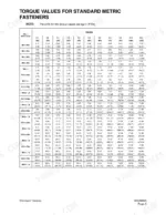
| General Maintenance | 53-80 | General Maintenance Procedures S0302000, Standard Torques S0309000 |
| Upper Structure | 81-142 | Cab S0402000, Counterweight S0403000, Fuel Tank S0405030, Fuel Transfer Pump S0405500, Swing Bearing S0407000, Swing Reduction Gearbox S0408030 |
| Lower Structure and Chassis | 143-170 | Track Assembly S0505060 |
| Engine and Drive Train | 171-210 | Air-Conditioner S0605010, Drive Coupling (Main Pump) S0609000 |
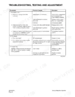
| Hydraulic System Troubleshooting, Testing and Adjustment S0702090 | 211-242 | Hydraulic System - General Notes, Operation of Working Components, Boom Operating Circuit, Arm Operating Circuit, Bucket Operating Circuit, Swing Operating Circuit |
| Accumulator S0703000 | 243-248 | General Description, Specifications, Accumulator Charging, Charging the Accumulator with Nitrogen |
| Center Joint (Swivel) S0704030 | 249-256 | General Description, Parts List, Troubleshooting, Testing and Adjustment, Inspection, Disassembly, Reassembly |
| Cylinders S0705000 | 257-276 | General Description, Theory of Operation, Parts List, Special Tools and Materials, Piston Nut, Piston Jig, Disassembly, Reassembly |
| Swing Motor S0707230 | 277-302 | General Description, Theory of Operation, Anti-Cavitation Make-Up Valve, Relief Valve, Swing Brake Operation, Parts List, Specifications, Disassembly, Wear Limits and Tolerances, Reassembly |
| Travel Motor (with Gearbox) S0707360 | 303-346 | General Description, Theory of Operation, Travel Motor Brake, Counterbalance Valve, Relief Valve, Travel Gearbox Parts List, Specifications, Two Speed Travel, Motor Rotation, Motor Lubrication |
| Main Pump (with Regulator) S0708360 | 347-380 | General Description, Gear (Pilot) Pump, Relief Valve, Pump Regulator Description, Horsepower Control, Power Shift Control, Negative Oil Discharge (Pump Bypass) Control, Pump Regulator Operation |
| Main Control Valve (DX36-101) S0709430 | 381-454 | Control Valve Operation, Arm Priority-Swing Circuitry, Bucket (Junction) Circuitry, Straight Travelling Circuit, Plunger Replacement, Main Relief Valve, Overload Relief Valve, Boom Load Holding Valve, Priority Valve, Boom Regeneration, Arm Regeneration |
| Pilot Control Valve (Work Lever / Joystick) S0709450 | 455-472 | General Description, Theory of Operation, Parts List, Specifications, Hydraulic Specifications, Special Tools, Disassembly, Reassembly |
| Travel Control Valve S0709800 | 473-500 | General Description, Theory of Operation, Parts List, Specifications, Torque Table, Troubleshooting, Testing and Adjustment, Disassembly, Wear Limits and Tolerances, Reassembly |
| Travel Control Valve (Jeil Hydraulics) S0709810 | 501-516 | General Description, Theory of Operation, Neutral Mode, Control Mode, Torque Table, Troubleshooting, Testing and Adjustment, Disassembly, Wear Limits and Tolerances, Reassembly |
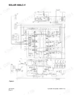
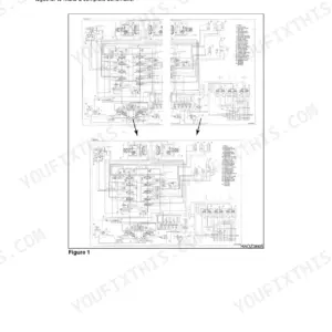
| Hydraulic Schematic (S400LC-V) S0792060 | 517-522 | General Description, Solar 400LC-V Hydraulic Schematic, General Notes |
| Electrical System S0802100 | 523-582 | Troubleshooting - Electrical System, Wiring Harness Illustrations, Electric Supply System, Engine Starting Circuit, Engine Preheating System, Engine Stop System, Charging System, Monitoring System, Instrument Panel |
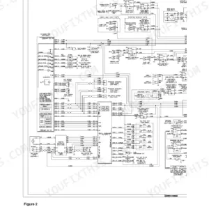
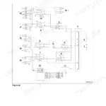
| Electrical Schematic (S400LC-V) S0892060 | 583-588 | General Description, Solar 400LC-V Electrical Schematic |
| Attachments | 589-612 | Boom and Arm S0902050, Bucket S0904000 |
Quick Reference Specifications
| Specification | Value | Page |
|---|---|---|
| Standard shoe width | 600 mm | p. 41 |
| Optional shoe width | 750 mm | p. 41 |
| Torque for 1/2" split flange | 15 - 18 ft lbs | p. 76 |
| Torque for 3/4" split flange | 22 - 27 ft lbs | p. 76 |
| Fuel Tank Capacity (400LC-V) | 535 liters (141 gal) | p. 105 |
| Recommended tension for operation over most types of terrain | 360 - 390 mm (14.17 - 15.35 in.) | p. 148 |
| Recommended clearance for muddy ground conditions | 390 - 410 mm (15.35 - 16.14 in.) | p. 148 |
| Lower roller, axle Dimension A (Normal New Dimension) | 85 mm (3.35 in.) | p. 150 |
| Lower roller, axle Dimension A (Recommended Limit for Maintenance) | 84.5 mm (3.33 in.) | p. 150 |
| Front idler, axle Dimension A (Normal New Dimension) | 85 mm (3.35 in.) | p. 152 |
| Front idler, axle Dimension A (Recommended Limit for Maintenance) | 84.5 mm (3.33 in.) | p. 152 |
Daewoo Solar 400LC-V Common Problems This Manual Covers
Daewoo Solar 400LC-V all hydraulic functions slow and weak, boom swing and travel sluggish
Check hydraulic oil level before pulling anything apart; the reservoir holds 255 liters, spec on page 41. Test main relief pressure and set it to 320 kg/sq cm per page 47. If pressure will not come up with a correct relief setting, measure pump discharge output; low flow points to a worn main pump rotating group.
Manual Section: Hydraulic System TroubleshootingSwing operates unevenly, drifts under load, or only rotates in one direction
Test swing relief valve pressure on both ports; spec is 270 to 280 bar, verified on page 234. Unequal readings mean one relief cartridge is off. Confirm the hydraulic brake releases at 4 bar, and check the motor makeup valve for its 2.5 bar cracking pressure per page 235. Replace worn swing motor parts only after pressures check good.
Manual Section: Swing System Troubleshooting p. 234Hydraulic oil overheating during normal digging, all functions turn sluggish once machine warms up
Drain and refill the reservoir with clean oil if contamination shows; capacity is 255 liters per page 41. Replace hydraulic filters, then verify main relief pressure sits at 320 kg/sq cm and not above, spec on page 47. An over-set relief dumps heat into the oil constantly. Check pump case drain flow for internal leakage.
Manual Section: Hydraulic System TroubleshootingHydraulic oil leaking from center joint between upper structure and travel motor lines
Inspect the center joint for external weeping and replace the O-rings and seals as a set, not one at a time. Clean every mating surface before assembly; one grain of grit ruins a new seal. Torque the 1-1/4 inch split flange connections to 35-45 ft lbs per page 76, and never judge tightness by pulling on a hose.
Manual Section: Hydraulics p. 211Tracks sag or come off on rough ground, rollers and idlers wearing fast
Measure track sag first; recommended tension is 360-390 mm for most terrain, per page 148. Check grouser height on the 600 mm shoes and replace pads worn past the 30 mm limit for use listed on page 149. Measure lower roller axles; anything under 84.2 mm per page 150 is finished. Adjust tension with the grease cylinder, not guesswork.
Manual Section: Lower Structure and Chassis p. 148Engine cranks slowly or won't start, battery not charging, intermittent electrical faults
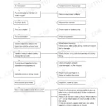
Start at the battery terminals and ground straps; corrosion there is behind most charging complaints. Test alternator output at the battery against the 24 V, 50 amp alternator spec on page 43. Then inspect harness chafe points at the cab entry and frame pass-throughs and trace suspect circuits on the electrical schematic, pages 583-588. For intermittent faults, read the malfunction codes on the EPOS-V controller display in the drawer under the operator's seat, page 577.
Manual Section: Electrical System p. 577Frequently Asked Questions
How do I clear a fault code on a Daewoo Solar 400LC-V?
For fault codes 1 through 6, you must correct the problem and then turn the starter switch from "OFF" to "ON" to reset the controller. For fault codes 7 through 16, the system will perform an automatic reset once the problem is corrected. p. 579
What are the torque specifications for the hydraulic pump bolts on a Solar 400LC-V?
Table 2 on page 208 gives the drive coupling torques by model. For the Solar 400LC-V (coupling 2414-9040) the insert bolts "Ta" go to 44 - 49 kg•m (318 - 354 ft lbs) and the hub clamping screws "Tb" to 20 - 22 kg•m (145 - 159 ft lbs), with "Measurement H" set to 5.0 - 6.0 mm (0.196 - 0.236 in.). The main pump itself is held by 17 mm allen-head hex bolts. p. 208
How do I check diagnostic codes on a Daewoo Solar 400LC-V?
You can check the system operation status and malfunction codes through the display on top of the EPOS-V control box, which is located in the drawer under the operator's seat. p. 577
What is the recommended interval for cleaning the air filtration system filter?
The air filtration system filter (1, Figure 2) should be cleaned out at approximately every 500 hours of operation. If the unit is operated in a dusty environment, cleaning and replacement should be performed more frequently. p. 175
What is the correct torque for the counterweight mounting bolts on a Solar 400LC-V?
For the Solar 400LC-V, the counterweight mounting bolts should be tightened to 250 kg•m (1,807 ft lbs). p. 99
Will this Daewoo Solar 400LC-V Shop Manual download right away?
Instant PDF download. You get the full 612-page searchable Shop Manual immediately after payment. Open it on your laptop, tablet, or phone right in the shop.
Can I print just the pages I need from this Daewoo Solar 400LC-V manual?
Yes. Print the pages you need for the job in your own shop, and bin them when they get greasy.


Reviews
There are no reviews yet.