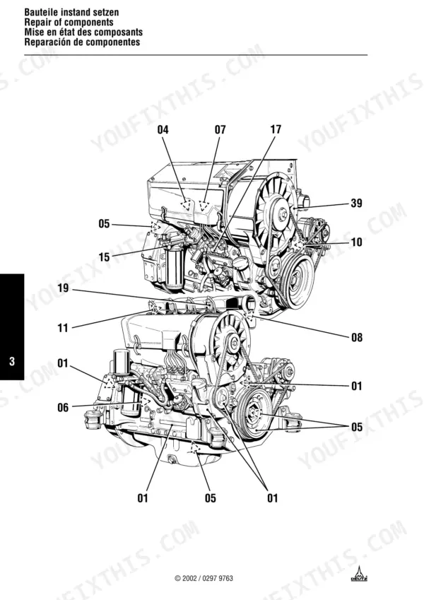
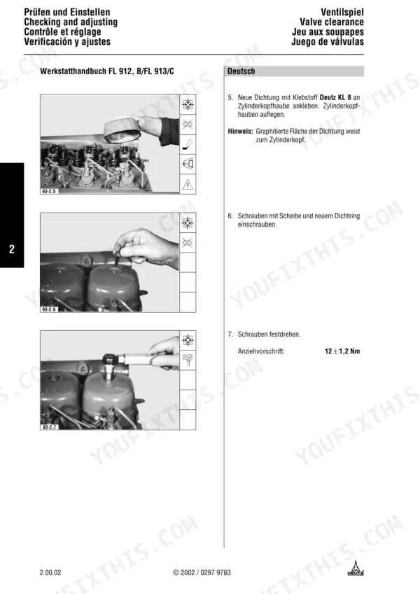
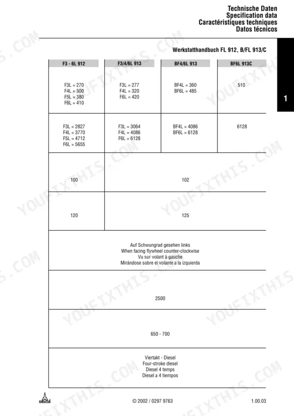
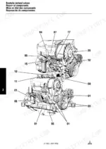
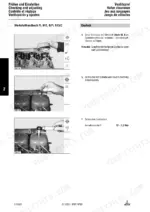
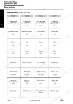
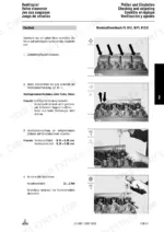
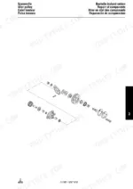
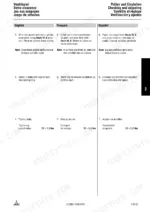
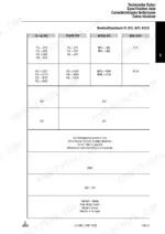

Measuring, adjusting and rebuilding Deutz 912 and 913 diesel engines is the job of this 433-page Deutz 912 workshop manual PDF (OEM ID 0297 9763), spanning four designations including the BF4L 913 and BF6L 913C. Its checking and adjusting chapter covers valve clearance, compression pressure, top dead center, commencement of delivery and injection pump testing. Repair work runs through the crankcase, crankshaft and mass balancing gear, piston ring gap and valve stem clearance, backed by exploded views, engine dismantling and reassembly, and a special tools listing. Some headings print in German. Check oil pressure at 650 rpm low idle with oil near 120°C on SAE 15W/40; injection pump drive bolts take 25 + 3 Nm. If your order list includes valve seat inserts or a small end bush, the cylinder head and connecting rod chapter shows the checks behind it. Bookmarks and a text layer find each clearance, so your head and bottom end go back together to Deutz's figures.
What's Inside This Deutz 912, 913 Manual
| System | Pages | Key Topics |
|---|---|---|
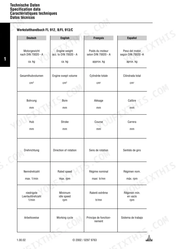
| Technische Daten | 9-23 | Techn. Daten (Ventilspieleinstellschema, Bildzeichenerklärung) |
| Prüfen Und Einstellen | 24-93 | Valve Clearance, Compression Pressure, Top Dead Center, Commencement of Delivery, Injector, Injection Pump, Exhaust Thermostat |
| Crankcase | 94-115 | Crankcase Cleaning, Oil Spray Nozzles, Cylinder Seating Surface, Camshaft Bearings |
| Idler Gear Bearing | 116-119 | Bearing Journal Inspection, Idler Gear Inspection, Bearing Clearance |
| Front and Rear Covers | 120-127 | Shaft Seal Removal, Cover Inspection, Gasket Remnants |
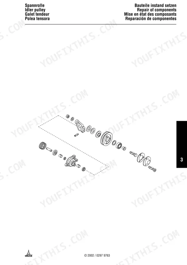
| Idler Pulley | 128-143 | V-Belt Pulley Removal, Bearing Bush Replacement, Shaft Seal Installation, Idler Pulley Lever |
| Cylinder | 144-149 | Cylinder Inspection, Cylinder Seating Surface, Wear Limits |
| Crankshaft and Mass Balancing Gear | 150-175 | Bearing Journal Hardness, Crankpin Measurement, Crankshaft True Running, Mass Balancing Gear Assembly |
| Connecting Rod, Piston, Cylinder Head | 176-213 | Small End Bush, Piston Ring Gap, Valve Stem Clearance, Valve Seat Inserts, Valve Spring Length |
| Camshaft, Rocker Arm Bracket, Change-Over Cock, Injection Pump, Blower | 214-277 | Camshaft Wear, Rocker Arm Bracket Inspection, Change-Over Cock Assembly, Injection Pump Testing, Blower Rotor and Bearings |
| Demontage Und Montage, Motor Komplett | 278-413 | Dismantling Engine, Reassembling Engine, Components Identical BF4L 913, Replacing Shaft Seal |
| Werkzeuge | 414-433 | Commercial Tools, Special Tools |
Quick Reference Specifications
| Specification | Value | Page |
|---|---|---|
| Lube oil pressure at low idling | 650 rpm, temperature approx 120°C, oil SAE 15W/40 | p. 16 |
| Lube oil pump capacity | 40 + 60 litres / min, 70 + 80 litres / min | p. 16 |
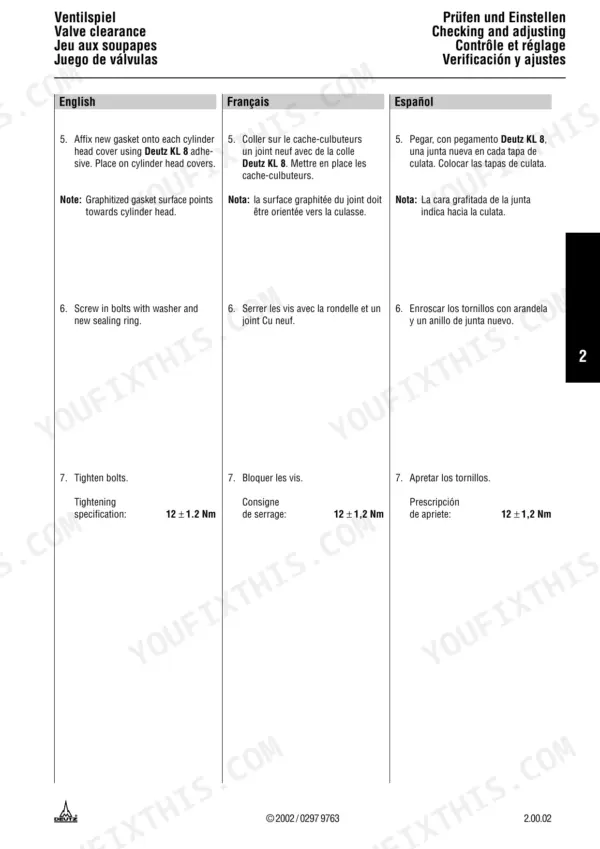
| Valve cover bolt torque | 12 ± 1.2 Nm | p. 29 |
| Cylinder head cover bolt torque | 12 ± 1.2 Nm | p. 51 |
| Injection pump drive bolt torque | 25 + 3 Nm | p. 63 |
| Injection line cap nut torque | 25 + 3 Nm | p. 65 |
| Lube oil pump backlash | 0.15 - 0.25 mm | p. 323 |
| Cylinder head bolt torque | Initial tightening torque 30 - 45 Nm, Tightening angles 45° + 45° + 45° + 30° | p. 341 |
| V-belt tension | Initial assembly 400 + 50 N, Check after 15 min operation under load 250 + 50 N, When reusing belt 250 + 50 N | p. 377 |
| Filter bracket tightening torque | 18 ± 1 Nm | p. 371 |
| Valve clearance (Inlet) | 0.15 + 0.05 mm | p. 27 |
Deutz 912, 913 Common Problems This Manual Covers
Deutz FL 912 B/FL 913 valve clearance out of specification when checked on a cold engine
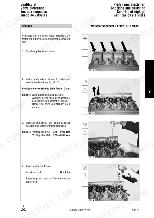
Verify the engine has cooled to ambient temperature first. Remove the cylinder head covers, crank until cylinder No. 1 valves overlap (neither pushrod turns), and set inlet and exhaust to 0.15 + 0.05 mm with a feeler gauge per page 27. Tighten the locknut to 22 ± 2 Nm, recheck, then torque covers to 12 ± 1.2 Nm per page 29.
Manual Section: Valve Clearance Adjustment p. 27Compression pressure varies more than 15 percent between cylinders during the starter cranking test
Remove the injectors, using the extracting device with adapter if they are jammed. Fit the connector with a new sealing ring, crank on the starter and record each cylinder against the 20-30 bar listed on page 33. Cranking speed and altitude skew readings, so compare cylinders. Over 15% difference, disassemble that cylinder unit per page 35. Refit injectors with new sealing rings at 25 + 5 Nm.
Manual Section: Compression Pressure Testing p. 35Injection nozzle opening pressure out of specification when checked on the nozzle tester
Connect the injector to the nozzle tester and slowly press the lever with the gauge switched on; the pressure where the pointer stops or suddenly drops is the opening pressure. Check it against 250 + 8 bar on page 67. Keep skin away from the nozzle fuel jet: it penetrates deep into tissue and can cause blood poisoning (page 67). Torque the nozzle tensioning nut to 40 + 10 Nm per page 69.
Manual Section: Injector Testing p. 67Injection pump commencement of delivery found incorrect when checking and setting injection timing
Check and set commencement of delivery following the Commencement of Delivery procedure in the Checking and Adjusting section. Torque the injection pump drive bolts to 25 + 3 Nm as page 63 specifies. Refit the injection lines with the rubber strip and tighten the cap nuts to 25 + 3 Nm per page 65. Do not guess these values; use the torque wrench.
Manual Section: Commencement of Delivery p. 63After replacing the V-belt pulley, top dead center mark no longer valid for timing
Remove the cylinder head cover from cylinder No. 1 and crank until its valves overlap (exhaust about to close, inlet about to open). Fit pointer 100 740 and redetermine top dead center with dial gauge 100 400 and adjusting device 100 640, following page 43. Reinstall the cover and torque its bolts to 12 ± 1.2 Nm per page 51.
Manual Section: Top Dead Center Determination p. 43V-belt tension dropping below the assembly value after the first 15 minutes under load
Tension a new V-belt to 400 + 50 N at assembly. Run the engine 15 minutes under load, then recheck tension against 250 + 50 N as page 377 specifies. When reusing an old belt, set it straight to 250 + 50 N. Retension any belt that reads outside its range before returning the engine to service.
Manual Section: Demontage Und Montage, Motor Komplett p. 377Frequently Asked Questions
What are the torque specifications for Deutz 912/913 cylinder-head bolts?
The cylinder head bolts for the Deutz 912/913 engine require a tightening torque of 30-45 Nm, followed by a tightening angle of 45° + 45° + 45° + 30°. p. 341
How do you set injection-pump timing on a Deutz 912/913?
Injection pump timing is set by turning the crankshaft in the opposite direction of engine rotation by 90°, then turning it in the direction of rotation until the specified commencement of delivery value coincides with the pointer. The injection pump drive bolts are then tightened to 25 + 3 Nm. p. 62
What are the valve-clearance specifications for a Deutz 912/913?
The valve clearance for both the inlet and exhaust valves on the Deutz 912/913 engine is 0.15 + 0.05 mm, measured with the engine cold. p. 27
How do you adjust the valves on a Deutz 912/913?
Adjust the valves only when the engine is cold. Crank the engine until the valves of cylinder No. 1 overlap, then adjust the clearance on the relevant cylinder using a feeler gauge to 0.15 + 0.05 mm and tighten the locknut to 22 ± 2 Nm. p. 27
What is the injector opening pressure specification for the Deutz 912, 913, FL 912, B/FL 913/C diesel engine?
The opening pressure for the injectors on the Deutz 912/913 engine is 250 + 8 bar. p. 67
What do I get after purchasing this Deutz 912 manual?
A 433-page Workshop Manual in searchable PDF format, available the moment you complete checkout. View on computer, tablet, or phone, with no shipping wait.
Can I print specific sections of this Deutz 912 Workshop Manual?
Yes. Print a single page or a chapter for your own shop use, on letter or A4.