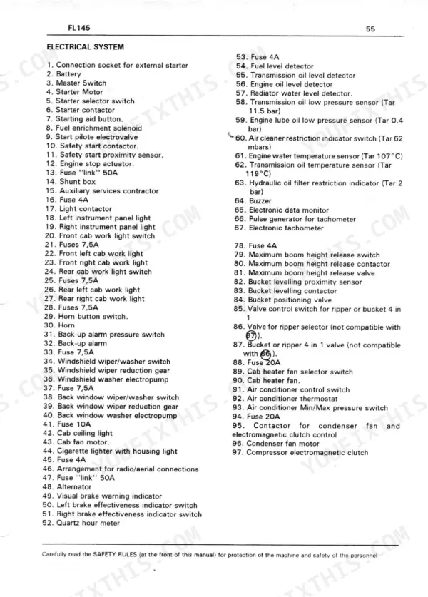
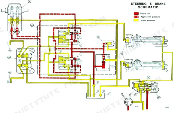
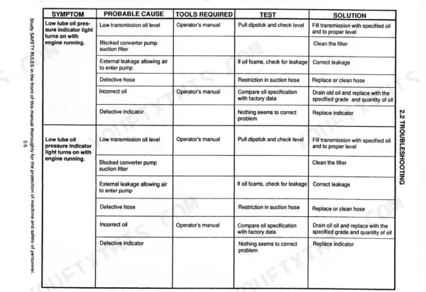
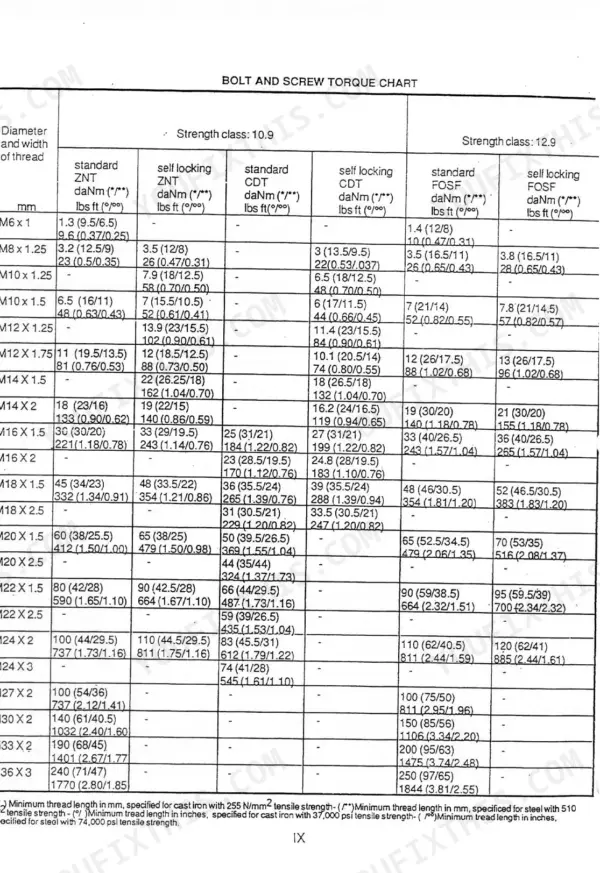
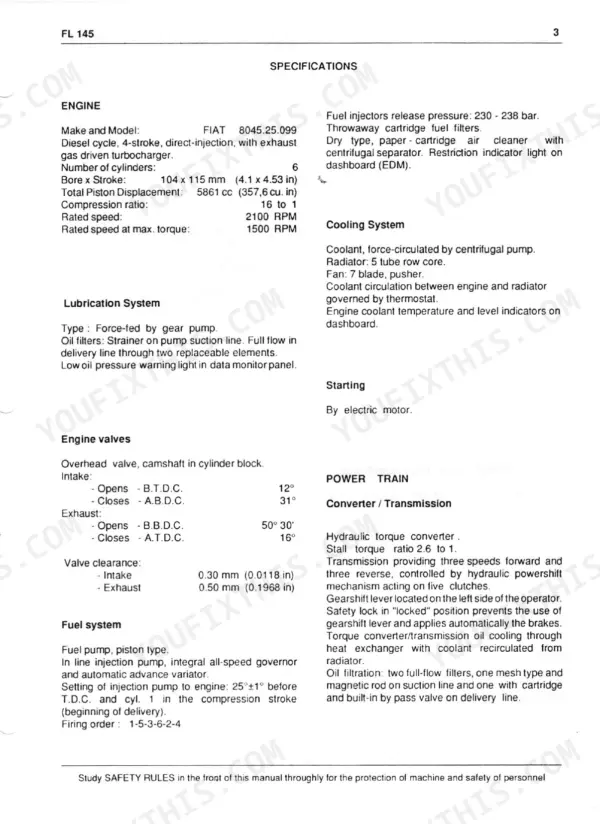
This 779-page FiatAllis FL145 Operation and Maintenance Instruction Manual, Service Manual (OEM #604.00.516, 73156192) covers the crawler loader from cab controls down to final drives. You get wiring diagrams for the full electrical system, hydraulic schematics covering the tank, pump, valve, and boom/bucket/ripper cylinders, plus a dedicated troubleshooting section for engine, transmission, and steering clutch faults. Inside you'll also find every maintenance interval laid out (250, 500, 1,000, and 2,000-hour services) alongside torque charts for bolts, screws, and nuts by material strength class. The attachment hydraulic system spec calls for oil filtered through two full-flow filters (metal gauze on suction, paper on return), and steering clutches run multi-disc oil-bath with hydraulic release control, exactly as your machine left the factory. No more guessing at fluid grades or chasing electrical gremlins with a test light. Bookmarked and searchable: jump straight to the section you need and get back to running the machine.
What's Inside This Manual
| System | Pages | Key Topics |
|---|
| Safety & Controls | 3-25 | Safety Rules, Controls and Instruments, Instrument Panel, General Notes |
| Machine Operation | 27-40 | Cold-Weather Starting, Operating Tips, Bucket Loading, Ripper Operation, Cab |
| Maintenance Schedule | 47-60 | 250-Hour, 500-Hour, 1000-Hour, 2000-Hour Services, When-Necessary Service, Lubrication |
| Electrical System (Operation) | 63-64 | Wiring Diagram, Lights, Fuses |
| Fluids & Torque Specifications | 67-82 | Oil Grades, Fluid Capacities, Standard Bolt/Nut Torque Charts |
| Engine Related Components | 84-137 | Engine, Cooling System, Fuel System, Lubrication, Removal and Installation, Troubleshooting |
| Transmission | 138-249 | Torque Converter, Clutch Packs, Controls, Overhaul, Troubleshooting |
| Final Drives | 250-293 | Final Drive, Sprocket, Planetary Gears, Bearings, Seals |
| Bevel Gear, Steering and Brakes | 294-402 | Bevel Gear, Steering Clutches, Steering Brakes, Service Brakes, Controls |
| Hydraulics | 403-468 | Hydraulic Tank, Hydraulic Pump, Control Valves, Lift/Tilt Cylinders, Lines and Fittings |
| Undercarriage | 469-530 | Track Chain, Track Rollers, Front Idler, Track Adjuster, Sprockets |
| Electrical System (Service) | 531-736 | Wiring, Connectors, Starting and Charging, Instruments, Lights, Sensors |
| Cab | 737-779 | Cab Tilting, Seat Assembly, Doors, Heating and A/C, Glass |
Quick Reference Specifications
| Specification | Value | Page |
|---|
| Hydraulic system performance loss (slow response or complete failure) | If controls or other hydraulic systems feel spongy have the machine checked for air in the systems. Presence of air in these systems could cause improper control and result in an accident. See the Operation and Maintenance Instruction Manual for corrective procedures. | p. 3 |
| Steering clutch | Multi - disc oil - bath steering clutches with hydraulic release control | p. 14 |
| Monobloc three spool control valve | includes: pressure relief valve, safety and make-up valves | p. 14 |
| Oil filtration | Two full flow filters, metal gauze on suction line; paper, with safety by - pass valve in case of restriction, on return line to reservoir | p. 14 |
| Sprockets | crown gear with replaceable rims | p. 14 |
| Track shoes (per track) | 35 | p. 2 |
| Cooling system mixture | 50-50 mixture of water and permanent type (glycol base) antifreeze for protection down to -35° C -31° F | p. 16 |
| Hydraulic system pressure release | Follow instructions in "Instruction manual" to release pressure before unscrewing cap. | p. 46 |
| Converter/transmission pressure pump suction line | Full flow, replaceable steel mesh elements and magnetic plug. | p. 249 |
| Bore for release plunger. Clearance | 0.443-0.123 | p. 389 |
| Pump body max. wear on inlet side in relation to gears | 0.1 | p. 391 |
| Maximum length of shim assembly for spool detents | 6mm (0.24 in) | p. 433 |