
Part of the Hitachi Repair Manuals.
All 305 pages of this Hitachi EX550–EX600 series service manual PDF focus on one job: tearing down and rebuilding your EX550-5, EX550LC-5, EX600H-5, or EX600LCH-5 hydraulic excavator to factory standard. You get step-by-step remove-and-install procedures for the main pump, control valve, swing device, travel motor, center joint, and boom cylinders, each backed by maintenance standards listing exact wear limits. A full torque chart and piping joint section covers the fasteners across the whole machine, from cab glass to track shoes. Pull the track frame mounting bolts down to 2160 N·m, and set the 1-3/16-12UNF ORS hydraulic fittings to 175 N·m. Swing motor whining? Tracks sagging? This is where the real answers live. Bookmarked with a live text layer: search any spec, jump straight to the procedure, and get wrenching.
What's Inside This Hitachi EX550-5, EX600H-5, EX550LC-5, EX600LCH-5 Manual
| System | Pages | Key Topics |
|---|---|---|
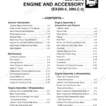
| Introduction | 1-2 | Manual Composition, Page Numbering, Safety Alert Symbols, Unit Conversion |
| Safety | 3-30 | Emergency Procedures, Protective Clothing, Fire Prevention, Machine Inspection, Maintenance Safety, Hazardous Fluid Handling |
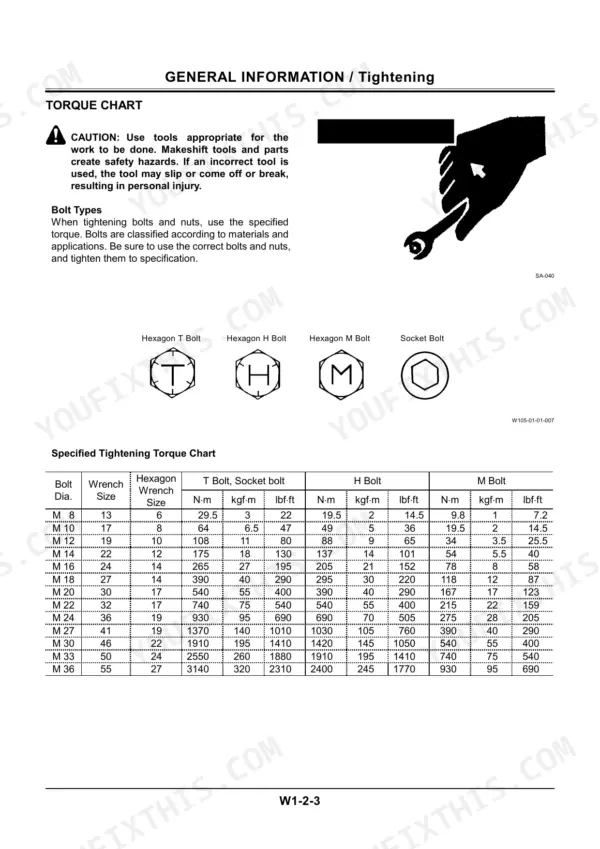
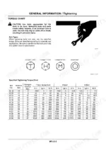
| General Information | 31-48 | Group 1 Precautions for Disassembling and Assembling (Maintenance Standard Terminol-Ogy), Group 2 Tightening (Tightening Torque Specifications, Torque Chart, Piping Joint) |
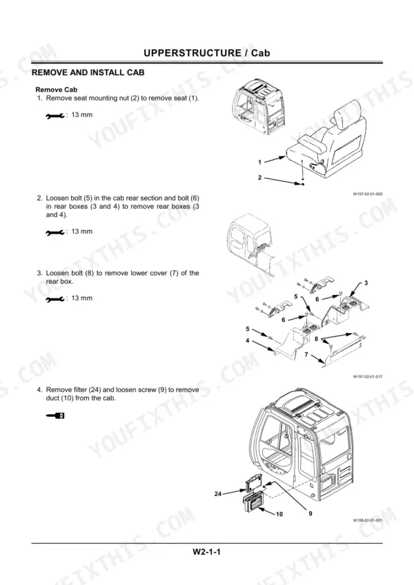
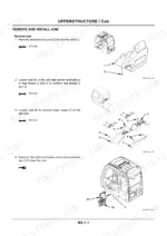
| Group 1 Cab | 51-58 | Remove and Install Cab, Dimensions of the Cab Glass |
| Group 2 Counterweight | 59-60 | Remove and Install Counter-Weight |
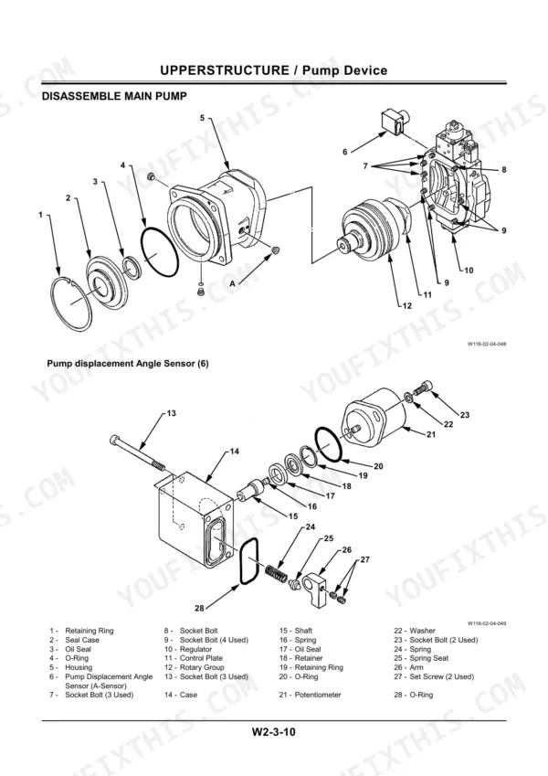
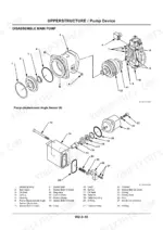
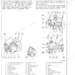
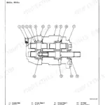
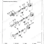
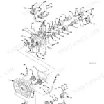
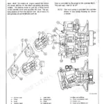
| Group 3 Pump Device | 61-86 | Remove and Install Pump Device, Disassemble Pump Transmission, Assemble Pump Transmission, Remove and Install Main Pump |
| Group 4 Control Valve | 87-126 | Remove and Install Control Valve, Disassemble Control Valve 1, Assemble Control Valve 1, Disassemble Control Valve 2 |
| Group 5 Swing Device | 127-148 | Remove and Install Swing Device, Disassemble Swing Device, Assemble Swing Device, Disassemble Swing Motor |
| Group 6 Pilot Valve | 149-168 | Remove and Install Right Pilot Valve (Front Attachment), Remove and Install Left Pilot Valve (Front Attachment), Remove and Install Travel Pilot Valve |
| Group 7 Pilot Shut-Off Valve | 169-176 | Remove and Install Pilot Shut-Off Valve, Disassemble Pilot Shut-Off Valve, Assemble Pilot Shut-Off Valve |
| Group 8 Solenoid Valve Unit Solenoid Valve EHC Valve | 177-182 | Remove and Install Three-Spool Solenoid Valve, Disassemble and Assemble Three-Spool Solenoid Valve 5 Valve |
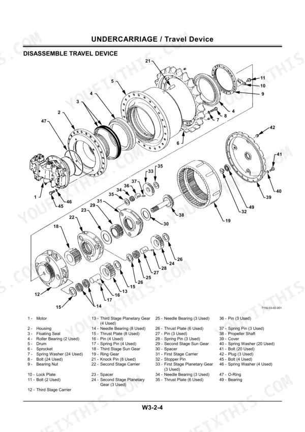
| Undercarriage | 183-278 | Group 1 Swing Bearing (Remove and Install Swing Bearing, Disassemble Swing Bearing, Assemble Swing Bearing) |
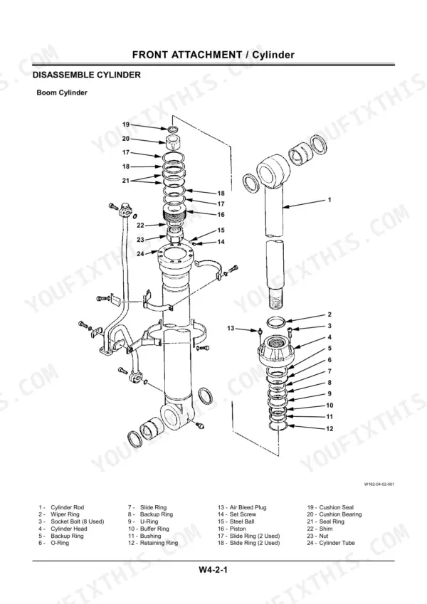
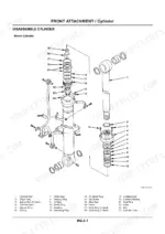
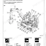
| Front Attachment | 279-304 | Group 1 Front Attachment (Preparation for Removing and In-Stalling Cylinder, Remove and Install Cylinder, Maintenance Standards, Air Bleeding Procedure) |
| Revision Request Form | 305 |
Quick Reference Specifications
| Specification | Value | Page |
|---|---|---|
| Track frame mounting bolt torque | 2160 N·m (225 kgf·m, 1590 lbf·ft) | p. 38 |
| ORS fittings for hydraulic hoses and piping (1-3/16-12UNF) | 175 N·m (18 kgf·m, 130 lbf·ft) | p. 37 |
| ORS fittings for hydraulic hoses and piping (1-7/16-12UNF) | 205 N·m (21 kgf·m, 152 lbf·ft) | p. 37 |
| Filter (24) installation torque | 4.9 N⋅m (0.5 kgf⋅m, 3.6 lbf⋅ft) | p. 54 |
| Hose (22 mm) torque | 69 N⋅m (50 lbf⋅ft) | p. 192 |
| Hose (27 mm) torque | 93 N⋅m (69 lbf⋅ft) | p. 192 |
| Bleeder plug tightening torque | 9.8 N⋅m | p. 291 |
| Boom cylinder weight | 515 kg | p. 297 |
| Arm cylinder weight | 800 kg | p. 297 |
| Cab Weight | 260 kg | p. 53 |
| Counterweight Weight | 10500 kg | p. 59 |
| Main Pump Weight | 125 kg | p. 62 |
Hitachi EX550-5, EX600H-5, EX550LC-5, EX600LCH-5 Common Problems This Manual Covers
Hitachi EX550-5 hydraulic functions weak and slow after oil change, boom barely lifts
Run all cylinders, swing, and travel lightly for 10 to 15 minutes to purge trapped air, then bleed the pilot circuit for about 5 minutes. Crack each cylinder bleeder plug, close it when oil runs clear, and torque it to 9.8 N·m per page 291. Recheck tank level after repositioning the front attachment.
Manual Section: Front Attachment p. 291Oil leaking from travel device housing and hoses, fresh oil film on tracks after every shift
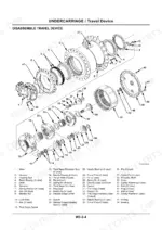
Steam clean the travel device, run it briefly, and trace the fresh leak to its source. Retighten loose hardware and replace damaged hoses; torque 27 mm hose fittings to 93 N·m per page 192. If the floating seal is weeping, pull the travel device for reseal. It weighs 850 kg, so rig it properly before unbolting.
Manual Section: Undercarriage p. 192Low digging power and slow cycle times on high hour machines, all functions affected
Verify engine speed first, then run relief pressure tests on each circuit before condemning parts. Low readings across every function point to the main pump or main relief valve, not cylinders. Inspect the control valve reliefs starting on page 87. If the pump tests bad, remove it per page 61; the main pump weighs 125 kg, so use a hoist.
Manual Section: Group 3 Pump Device p. 61Boom and arm cylinders drift down under load, bucket settles within minutes of parking
Warm the oil, raise the boom, and mark rod position against the barrel. Steady creep with controls in neutral points to internal cylinder leakage past the piston seals. Swap relief valves between circuits to rule out a valve fault before pulling a cylinder. Reseal per the Front Attachment procedures starting on page 279; the boom cylinder alone weighs 515 kg.
Manual Section: Front Attachment p. 279Track frame bolts loose or missing, undercarriage hardware backing out during travel
Check track frame mounting bolts at every service interval and retorque loose ones to 2160 N·m (1590 lbf·ft) per the torque chart on page 38. Replace missing bolts in matched sets, never singles, since remaining bolts stretch under the extra load. While underneath, inspect the track adjuster and idler mounts using the Undercarriage procedures starting on page 183.
Manual Section: General Information p. 38Frequently Asked Questions
What is the tightening torque for the main pump mounting bolts on the EX550-5?
The main pump mounting bolts on the EX550-5 must be tightened to 390 N⋅m (40 kgf⋅m, 290 lbf⋅ft). p. 69
What is the procedure for bleeding air from the hydraulic pump?
To bleed air from the hydraulic pump, remove the air bleeding plug from the top of the pump and fill the pump housing with hydraulic oil. Temporarily tighten the plug, start the engine, and run at slow idle speed. Slightly loosen the plug until hydraulic oil oozes out, then securely tighten the plug. p. 34
What is the gear oil capacity for the swing device?
The gear oil capacity for the swing device is 13.2 L (3.49 US gal.). p. 137
What is the tightening torque for the swing device mounting bolts?
The tightening torque for the swing device mounting bolts is 740 N⋅m (75 kgf⋅m, 540 lbf⋅ft). p. 128
What is the required gear oil capacity for the travel device?
The required gear oil capacity for the travel device is 14 L (14.8 US qt). p. 203
What format is this Hitachi EX550–EX600 Series manual in?
You get a 305-page searchable PDF that downloads instantly after checkout. Open it on your laptop, tablet, or phone, and bring it right to the shop floor.
Can I print pages of this Hitachi EX550–EX600 Series manual for my own shop?
Yes. Print a chapter or just the pages for the job at hand, for use in your own shop. Any home or office printer works.

Reviews
There are no reviews yet.