
Part of the Hitachi Repair Manuals.
Complete factory library for the Hitachi EX60-5 and the ultra-short-swing EX75UR-3 / EX75URLC-3: Technical Manual with per-model specifications, control/hydraulic/electrical system theory and component operation, full circuit diagram and harness set, Operational Performance Test standards, structured Troubleshooting, and the Workshop Manual covering upperstructure, undercarriage, front attachment and the Nissan diesel.
What's Inside This Hitachi EX60-5 / EX75UR-3 / EX75URLC-3 Repair Manual
| System | Pages | Key Topics |
|---|---|---|
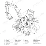
| General & Machine Specifications | 5-34 | Machine and Engine Specifications per Model (EX60-5 / EX75UR-3 / EX75URLC-3), Component Layout, Component Specifications |
| Control, Hydraulic & Electrical System | 35-106 | Control System and Front Control System Operation, Hydraulic System Circuits, Electrical System |
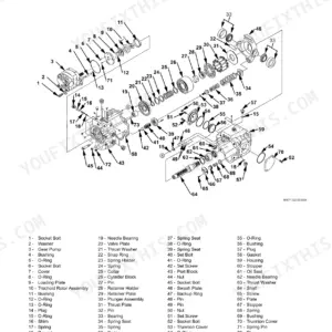
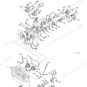
| Component Operation | 107-188 | Pump Device and Swing Device, Control Valve, Pilot Valve, Travel Device, Upperstructure and Undercarriage Components |
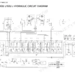
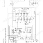
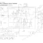
| Circuit Diagrams & Harness | 190-205 | Electrical Circuit Diagrams per Model, Hydraulic Circuit Diagrams (Incl. Blade), Cab and Engine Harness Routing |
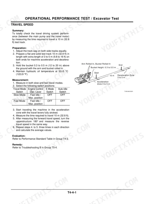
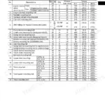
| Operational Performance Tests | 208-273 | Performance Standards Tables, Engine and Excavator Tests, Component Tests and Adjustment |
| Troubleshooting | 274-431 | Troubleshooting Procedures A-D, Component Layout for Diagnosis, Electrical System Inspection |
| Workshop: General Information | 463-480 | Disassembly and Assembly Precautions, Maintenance Standards, Tightening Torque Tables |
| Workshop: Upperstructure | 481-728 | Cab, Counterweight, Main Frame, Pump Device, Control Valve, Swing Device Removal and Install, Pilot, Solenoid and Relief Valves |
| Workshop: Undercarriage | 729-828 | Swing Bearing and Travel Device, Center Joint and Track Adjuster, Front Idler, Rollers and Track |
| Workshop: Front Attachment | 829-898 | Boom, Arm and Bucket Removal and Install, Cylinder Disassembly and Seals |
| Workshop: Engine & Accessory | 899-1004 | Engine Removal and Installation, Radiator and Accessory Service |
Quick Reference Specifications
| Specification | Value | Page |
|---|---|---|
| EX60-5 | ||
| Rated Power, EX60-5 | 41 kW (55 PS) at 2200 min⁻¹ | p. 7 |
| Max Torque, EX60-5 | 181 N·m (18.5 kgf-m, 135 lbf·ft) or more at 1500 min⁻¹ | p. 28 |
| Rated RPM, EX60-5 | 2200 min⁻¹ | p. 7 |
| Hydraulic Pump Flow (Main Pump) | 79.2 L/min (20.9 US gpm) | p. 30 |
| System Pressure (Swing Parking Brake Cracking Pressure), EX60-5 | 1.18 ± 0.15 MPa (12 ± 1.5 kgf/cm², 171 ± 21 psi) | p. 31 |
| Overall Length (1.62m Standard Arm Backhoe) | 6080 mm (19' 11") | p. 10 |
| Overall Length (1.62m Standard Arm Backhoe With Blade) | 6330 mm (20' 9") | p. 10 |
| Overall Length (1.62m Standard Arm Face Shovel) | 6080 mm (19' 11") | p. 10 |
| Overall Length (1.62m Standard Arm Face Shovel With Blade) | 6330 mm (20' 9") | p. 10 |
| Overall Length (2.12m Long Arm Backhoe) | 6120 mm (20' 1") | p. 10 |
| Overall Length (2.12m Long Arm Backhoe With Blade) | 6370 mm (20' 11") | p. 10 |
| Overall Length (2.12m Long Arm Face Shovel) | 6120 mm (20' 1") | p. 10 |
| Overall Length (2.12m Long Arm Face Shovel With Blade) | 6370 mm (20' 11") | p. 10 |
| Overall Width (Standard) | 2340 mm (7' 8") | p. 7 |
| Overall Width (With Blade) | 2390 mm (7' 10") | p. 7 |
| Overall Width of Upperstructure | 2255 mm (7' 5") | p. 7 |
| Undercarriage Width, EX60-5 | 2200 mm (7' 3") | p. 7 |
| Overall Height (Cab Height), EX60-5 | 2570 mm (8' 5") | p. 7 |
| Overall Height (Engine Cover Height), EX60-5 | *1690 mm (5' 7") | p. 7 |
| Overall Height (Transport Height, 1.62m Standard Arm Backhoe) | 2570 mm (8' 5") | p. 10 |
| Overall Height (Transport Height, 1.62m Standard Arm Face Shovel) | 2570 mm (8' 5") | p. 10 |
| Overall Height (Transport Height, 2.12m Long Arm Backhoe W/O Bucket) | 2690 mm (8' 10") | p. 10 |
| EX75UR-3 | ||
| Rated Power, EX75UR-3 | 40.5 kW (55 PS) at 2000 min⁻¹ | p. 8 |
| Rated RPM, EX75UR-3 | 2000 min⁻¹ | p. 8 |
| System Pressure (Control Valve Main Relief, Front and Swing) | 26.0 MPa (265 kgf/cm², 3770 psi) at 54 L/min | p. 30 |
| System Pressure (Control Valve Main Relief, Travel), EX75UR-3 | 22.6 MPa (230 kgf/cm², 3270 psi) at 48 L/min | p. 30 |
| System Pressure (Control Valve Overload Relief) | 27.9 MPa (285 kgf/cm², 4055 psi) at 20 L/min | p. 30 |
| System Pressure (Control Valve for Blade Main Relief) | 22.6 MPa (230 kgf/cm², 3270 psi) at 24 L/min | p. 31 |
| System Pressure (Control Valve for Blade Overload Relief) | 27.9 MPa (285 kgf/cm², 4055 psi) at 18 L/min | p. 31 |
| System Pressure (Travel Brake Valve Relief Pressure), EX75UR-3 | 28.9 MPa (295 kgf/cm², 4190 psi) at 40 L/min | p. 32 |
| System Pressure (Travel Parking Brake Cracking Pressure), EX75UR-3 | 0.78 MPa (8.0 kgf/cm², 115 psi) | p. 32 |
| System Pressure (7-Spool Solenoid Valve Specified Pressure) | 3.7 MPa (38 kgf/cm³, 54 psi) | p. 32 |
| Overall Length, EX75UR-3 | 6110 mm (20' 1") | p. 11 |
| Overall Width | 2280 mm (7' 6") | p. 8 |
| Undercarriage Width, EX75UR-3 | 2300 mm (7' 7") | p. 8 |
| Overall Height (Cab Height), EX75UR-3 | 2700 mm (8' 10") | p. 8 |
| Overall Height (Engine Cover Height), EX75UR-3 | 1705 mm (5' 7") | p. 8 |
| EX75URLC-3 | ||
| Rated Power, EX75URLC-3 | 40.5 kW (55 PS) at 2000 min⁻¹ | p. 9 |
| Rated RPM, EX75URLC-3 | 2000 min⁻¹ | p. 9 |
| System Pressure (Control Valve for Precise Swing Main Relief) | 21.6 MPa (220 kgf/cm², 3130 psi) at 24 L/min | p. 31 |
| System Pressure (Control Valve for Precise Swing Overload Relief) | 24.5 MPa (250 kgf/cm², 3560 psi) at 18 L/min | p. 31 |
| Overall Length, EX75URLC-3 | 6020 mm (19' 9") | p. 12 |
| Overall Width | 2280 mm (7' 6") | p. 9 |
| Undercarriage Width, EX75URLC-3 | 2300 mm (7' 7") | p. 9 |
| Overall Height (Cab Height), EX75URLC-3 | 2710 mm (8' 11") | p. 9 |
| Overall Height (Engine Cover Height), EX75URLC-3 | *1680 mm (5' 6") | p. 9 |
| EX75UR-3, EX75URLC-3 | ||
| Max Torque (EX75UR-3, EX75URLC-3) | 193 N·m (19.7 kgf-m, 142 lbf·ft) or more at 1800 min⁻¹ | p. 28 |
| Hydraulic Pump Flow (Main Pump 1) | 72 L/min (19 US gpm) | p. 30 |
| System Pressure (Swing Parking Brake Cracking Pressure) (EX75UR-3, EX75URLC-3) | 1.5 MPa (15 kgf/cm², 210 psi) | p. 31 |
| All Models | ||
| Coolant Capacity (Radiator) | 3.8 L (1.0 US gal) | p. 30 |
| Coolant Capacity (Oil Cooler) | 2.7 L (0.7 US gal) | p. 30 |
| Hydraulic Pump Flow (Pilot Pump) | 23.5 L/min (6.2 US gpm) | p. 30 |
| System Pressure (Swing Brake Valve Relief Pressure) | 25 MPa (255 kgf/cm², 3625 psi) at 63 L/min | p. 31 |
| System Pressure (Oil Cooler Bypass Check Valve Cracking Pressure) | 294 kPa (3.0 kgf/cm², 43 psi) at 5 L/min | p. 32 |
| EX75UR-3 (for blade), EX75URLC-3 (for precise swing) | ||
| Hydraulic Pump Flow (Main Pump 2) | 24.2 L/min (6.4 US gpm) | p. 30 |
| EX60-5, EX75URLC-3 | ||
| System Pressure (Control Valve Main Relief, Front and Swing) | 26.0 MPa (265 kgf/cm², 3770 psi) at 54 L/min | p. 30 |
| System Pressure (Control Valve Main Relief, Travel) (EX60-5, EX75URLC-3) | 31.4 MPa (320 kgf/cm², 4550 psi) at 42 L/min | p. 30 |
| System Pressure (Control Valve Overload Relief) | 27.9 MPa (285 kgf/cm², 4055 psi) at 20 L/min | p. 30 |
| System Pressure (Travel Brake Valve Relief Pressure) (EX60-5, EX75URLC-3) | 31.9 MPa (325 kgf/cm², 4620 psi) | p. 32 |
| System Pressure (Travel Parking Brake Cracking Pressure) (EX60-5, EX75URLC-3) | 0.88 MPa (9.0 kgf/cm², 128 psi) | p. 32 |
Hitachi EX60-5 / EX75UR-3 / EX75URLC-3 Common Problems This Manual Covers
Hydraulic overheating and sluggish digging even with clean filters
Run the pump flow and relief pressure tests in Operational Performance Tests against the standards tables. A pump delivering well under the rated 79.2 L/min (EX60-5) is bypassing internally and making heat; also check the oil cooler bypass check valve, cracking pressure 294 kPa, for a stuck open condition.
Manual Section: Operational Performance Tests (pages 208 to 273)Engine dies under high load or will not restart hot
On these Nissan diesels that is usually fuel delivery: air in the lines, a tired lift pump or injectors. Troubleshooting procedures A to D walk symptom by symptom to the cause, and Workshop: Engine and Accessory covers injector and fuel system service plus full engine removal if it comes to that.
Manual Section: Troubleshooting (pages 274 to 431)Swing brake drags or releases late, giving jerky rotation
Test the parking brake release pressure at the swing device, spec is 1.18 MPa on EX60-5 and 1.5 MPa on the UR machines. Low pilot pressure points to the solenoid valve or pilot circuit; correct pressure with dragging means brake plates, covered in the swing device teardown in Workshop: Upperstructure.
Manual Section: Workshop: Upperstructure (pages 481 to 728)Track thrown or loose, front idler and roller wear
Workshop: Undercarriage gives track adjuster service, front idler and roller replacement and the track removal procedure, with wear limits in the maintenance standards tables so you can measure link pitch and roller diameter and decide repair versus replace instead of eyeballing it.
Manual Section: Workshop: Undercarriage (pages 729 to 828)Frequently Asked Questions
My EX60-5 is down on power and the hydraulic oil runs hot after an hour of digging. Where do I start?
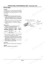
Start with the Operational Performance Tests section (pages 208 to 273). Run the pump delivery and relief pressure checks against the standards tables before pulling anything apart. The book lists main relief at 26.0 MPa for front and swing and 31.4 MPa for travel on the EX60-5, so if your gauge reads low you know whether it is the pump wearing out or a relief valve set wrong. Nine times out of ten heat plus weak digging is a worn pump bypassing oil, and the flow test tells you without guessing.
Does this cover the swing brake and jerky swing problems on the UR-3 machines?
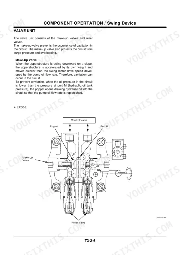
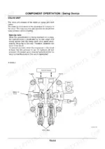
Yes. Component Operation (pages 107 to 188) explains how the swing device and swing brake valve actually work, including the parking brake release circuit, and the specs section gives you the cracking pressures to test against: 1.18 MPa on the EX60-5 and 1.5 MPa on the EX75UR-3 and URLC-3. If the brake sticks and the house jerks on takeoff, you check pilot pressure at the brake port first. Workshop: Upperstructure then walks the swing device removal, teardown and seal replacement.
Are the electrical schematics and wiring harness drawings for all three models included?
Yes, pages 190 to 205 carry the electrical circuit diagrams per model plus the hydraulic circuit diagrams including the blade circuit, and the cab and engine harness routing drawings. These are mechanical era machines, no laptop plugs in, so chasing a no start or a dead solenoid means a test light, a meter and the correct schematic. The Troubleshooting section adds an electrical system inspection procedure and component layout drawings so you can actually find the relay you are testing.
Will this get me through a boom or arm cylinder reseal?
Workshop: Front Attachment (pages 829 to 898) covers boom, arm and bucket removal and install plus cylinder disassembly and seal replacement. The specs list cylinder weights for rigging, the arm cylinder on the UR-3 is 85 kg for example, so you know what your hoist is picking. Torque values for gland nuts and mounting hardware are in the tightening torque tables in Workshop General Information.
The EX75UR-3 and URLC-3 have different hydraulics than the EX60-5. Does the manual separate them?
It does, and this matters. The EX60-5 runs one main pump at 79.2 L/min while the UR-3 machines run a 72 L/min main pump plus a 24.2 L/min second pump, feeding the blade on the UR-3 and the precise swing circuit on the URLC-3. Relief settings differ too, travel relief is 31.4 MPa on the EX60-5 and URLC-3 but 22.6 MPa on the UR-3. Every spec table and circuit diagram is broken out per model so you are never testing against the wrong number.
Reviews
There are no reviews yet.