
Part of the Hitachi Repair Manuals.
Looking for the Hitachi 33u technical manual PDF? All 533 pages here serve the Hitachi EX33u, 33u, and 30-2 hydraulic excavators, bundling the technical manual, workshop manual, and full engine service section in one download. You get the complete electrical circuit diagram, hydraulic schematics with main and pilot line routing, factory torque charts, and a full troubleshooting section for the engine control, monitor, and machine operation systems. Inside: pump device, swing device, control valve, and pilot valve teardowns, plus performance test standards and cylinder rebuild procedures. Test main pump delivery pressure against the 220 kgf/cm2 standard, and fail any boom cylinder that drifts past 10 mm in five minutes. Your excavator is down and the clock is running. Get factory numbers, not forum guesses. Bookmarked and keyword-searchable; pull it up on your phone next to the machine and start wrenching.
Complete the set for your EX33U
- Parts Catalog: Hitachi EX33U Parts Catalog
What's Inside This Hitachi EX33U Manual
| System | Pages | Key Topics |
|---|---|---|
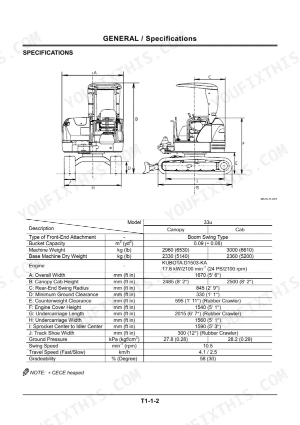
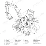
| Technical Manual - General | 2-9 | Machine Outline, Specifications, Working Ranges, Component Layout, Serial Numbers |
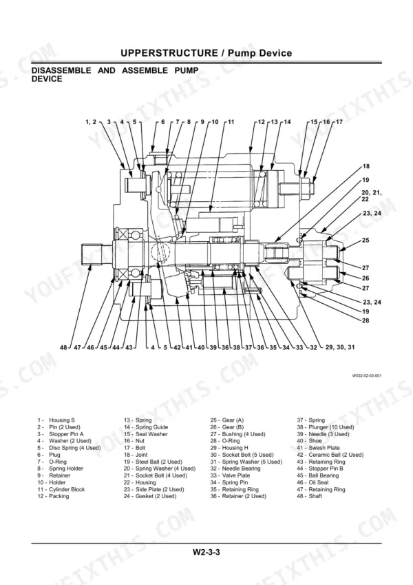
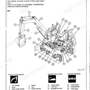
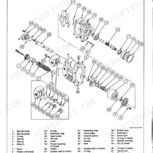
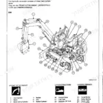
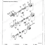
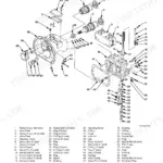
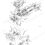
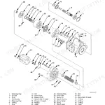
| Technical Manual - Upperstructure | 10-39 | Pump Device, Swing Device, Control Valve, Pilot Valve, Cylinders, Swivel Joint |
| Technical Manual - Undercarriage | 40-57 | Travel Device Specifications, Track Frame, Rollers and Idlers, Track Adjuster |
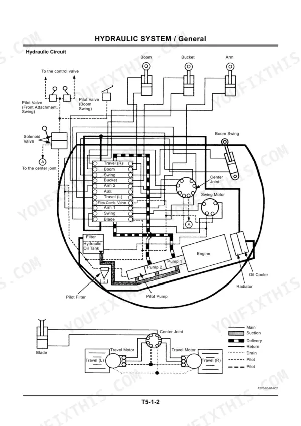
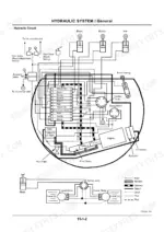
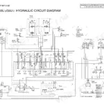
| Technical Manual - Electrical and Hydraulic Systems | 58-65 | Electrical Part Layout, Monitor Panel, Switches and Sensors, Hydraulic System Outline, Main and Pilot Lines |
| Technical Manual - Operational Performance Test | 66-97 | Engine Test, Excavator Test, Component Tests, Standard Values and Adjustment |
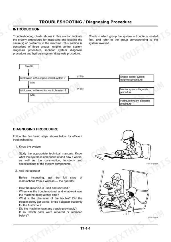
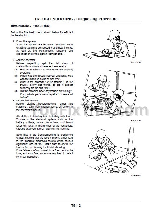
| Technical Manual - Troubleshooting | 98-142 | Diagnosing Procedure, Engine Control System Faults, Hydraulic and Electrical Troubleshooting Charts |
| EX33U Electrical Circuit Diagram | 143-144 | Battery and Starter Circuit, Engine Control, Monitor and Sensor Wiring, Full Machine Schematic |
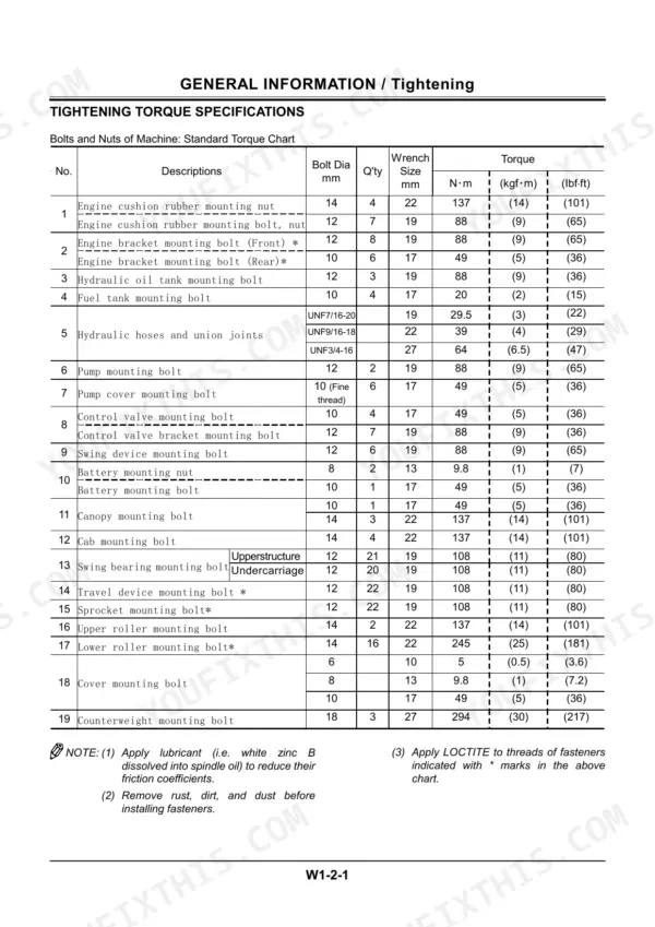
| Workshop Manual - General Information | 145-163 | Precautions for Disassembling and Assembling, Tightening Torques, Special Tools, Sealants |
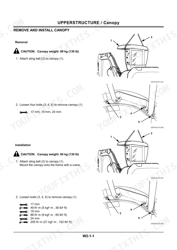
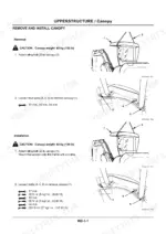
| Workshop Manual - Upperstructure | 164-243 | Canopy and Counterweight Removal, Hydraulic Pump, Swing Device, Control Valve, Cylinders, Swivel Joint Disassembly and Assembly |
| Workshop Manual - Undercarriage | 244-299 | Swing Bearing Removal, Travel Device Disassembly and Assembly, Track Frame, Rollers, Idler and Adjuster |
| Workshop Manual - Front Attachment | 300-333 | Boom, Arm and Bucket Removal, Pins and Bushings, Front Attachment Maintenance and Wear Limits |
| Engine - Full Repair Section (Bundled Engine Manual) | 334-533 | Engine Safety Instructions, Specifications and Performance Curves, Disassembly and Reassembly, Cylinder Head and Valves, Piston and Crankshaft, Lubrication, Cooling and Fuel Systems, Wear Limits and Torque Values |
Quick Reference Specifications
| Specification | Value | Page |
|---|---|---|
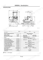
| Ground Pressure | 27.8 (0.28) kPa (kgf/cm²) for Canopy, 28.2 (0.29) kPa (kgf/cm²) for Cab | p. 5 |
| Main pump delivery pressure | 220 kgf/cm² | p. 97 |
| DIG DRIFT CHECK Boom Cylinder (Retraction) | 10 or less | p. 97 |
| DIG DRIFT CHECK Arm Cylinder (Extension) | 10 or less | p. 97 |
| Low engine oil pressure indicator stays ON | Check if oil filter is clogged or not. | p. 116 |
| Pilot primary pressure | 65 kgf/cm² or more | p. 127 |
| Low-pressure-hose clamp tightening torque (T-Bolt Type Band Clamp) | 4.4 N·m (0.45 kgf·m, 3.25 lbf·ft) | p. 160 |
| Low-pressure-hose clamp tightening torque (Worm Gear Type Band Clamp) | 5.9 to 6.9 N·m (0.6 to 0.7 kg.m, 4.3 to 5.1 lbf·ft) | p. 160 |
| Clearance between cylinder block bore and plunger | 0.050 mm or less | p. 181 |
| Clearance between plunger tip and shoe bottom | 0.2 mm or less | p. 181 |
| Socket bolts (6) torque | 3.3 to 4.4 N-m (0.35 to 0.45 kgf·m, 2.5 to 3.3 lbf-ft) | p. 240 |
| Bucket Capacity | 0.09 m3 | p. 5 |
Hitachi EX33U Common Problems This Manual Covers
Hitachi EX33u main pump delivery pressure below 220 kgf/cm2 spec, digging power weak and cycle times slow
Test relief pressure at the main line first; the standard setting is 220 plus or minus 10 kgf/cm2 per the performance standard table on page 97. If pressure stays low after adjustment, pull the pump and measure cylinder block bore to plunger clearance on page 181; replace the rotating group when clearance exceeds 0.050 mm.
Manual Section: Operational Performance Test (Technical Manual) p. 97Boom or arm cylinder drifts down with controls in neutral, bucket settles more than allowable
Run the dig drift check on page 97 with the bucket loaded and oil at operating temperature; allowable drift for boom, arm, and bucket cylinders is 10 mm or less. If a cylinder fails the check, reseal it using the cylinder disassembly procedure in the Front Attachment section, then torque the boom cylinder hoses to 39 N·m per page 318.
Manual Section: Front Attachment p. 97All hydraulic functions slow and unresponsive until oil warms up, pilot pressure will not hold
Warm the hydraulic oil fully, then tee a gauge into the pilot circuit and check for 65 plus or minus 10 kgf/cm2 as listed on page 97. Confirm primary pilot pressure reads 65 kgf/cm2 or more using the actuator troubleshooting steps on page 127; if it drops when warm, replace the pilot relief valve or worn pump.
Manual Section: Actuator System Troubleshooting p. 127Hydraulic oil leaking at hose clamps and fittings, wet spots under machine after each shift
Inspect every clamp and fitting with the engine off and system pressure released. Tighten worm gear band clamps to 5.9 to 6.9 N·m and T-bolt band clamps to 4.4 N·m per page 160. Replace any kinked or cracked hoses; pump suction, delivery, and cylinder line hoses are due every 2 years on the maintenance schedule, page 162.
Manual Section: General Information (Workshop Manual) p. 160Starter turns engine over but engine will not fire, or starter does not engage at all
Check the fuel injection pump stop solenoid and safety relay before pulling the starter; trace both circuits with the wiring diagram on page 143. Verify battery connections are clean and tight, and confirm fuel reaches the injection pump. When reinstalling the stop solenoid, torque its socket bolts to 3.3 to 4.4 N·m as specified on page 240.
Manual Section: Troubleshooting (Technical Manual) p. 143Frequently Asked Questions
What are the recommended service intervals?
The manual lists various service intervals for different components. For example, fuel hoses (fuel tank to filter and injection pump) and heater hoses should be replaced every 2 years. Engine oil (90 mm depth) should be changed every 75 hours, while the oil filter cartridge should be changed every 200 hours. Checking valve clearance is recommended every 500 hours. p. 162
What fluids and capacities does this machine require?
The machine uses Diesel Fuel No. 2-D (ASTM D975). The bucket capacity is 0.09 m3 (0.08 yd3 CECE heaped). The engine oil pan capacity is 5.6 US gallons (1.48 US gals, 1.23 Imp gals) for a 90 mm depth and 7.0 US gallons (1.85 US gals, 1.54 Imp gals) for a 124 mm depth. The travel device requires 0.5 L of gear oil. p. 338
How to troubleshoot engine won't start?
If the starter rotates but the engine does not fire, check if the voltage at the fuel pump connector is 12 V. If it's 0 V, there might be a faulty harness break or short circuit. If the starter does not rotate, check the battery voltage and electrolyte density. If terminal B on the starter is below 12 V, the battery may be faulty, or if terminal #50 is below 12 V, the starter may be faulty. p. 104
What are the valve clearance specifications?
The valve clearance (IN, EX) for the engine, when cold, should be between 0.18 to 0.22 mm (0.0071 to 0.0087 in.). This specification is crucial for proper engine operation and should be checked and adjusted if necessary. p. 339
What torque specifications are listed?
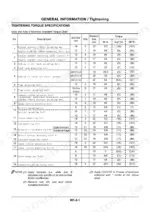
The manual provides a detailed torque chart for various bolts and nuts. For instance, an M14 engine cushion rubber mounting nut requires 137 N·m (14 kgf·m, 101 lbf·ft) of torque. A fuel tank mounting bolt (M10) should be tightened to 20 N·m (2 kgf·m, 15 lbf·ft). p. 153
What exactly do I receive with this Hitachi EX33U Technical Manual?
A 533-page Technical Manual in searchable PDF format, available the moment you complete checkout. View on computer, tablet, or phone, with no shipping wait.
Can I print pages of this manual for my own shop?
Yes. Print individual pages or full chapters for your own shop use, on letter or A4 paper.
Reviews
There are no reviews yet.