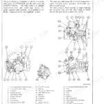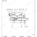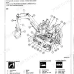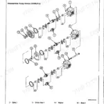


Part of the Hitachi Repair Manuals.
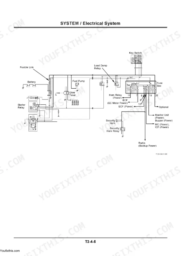
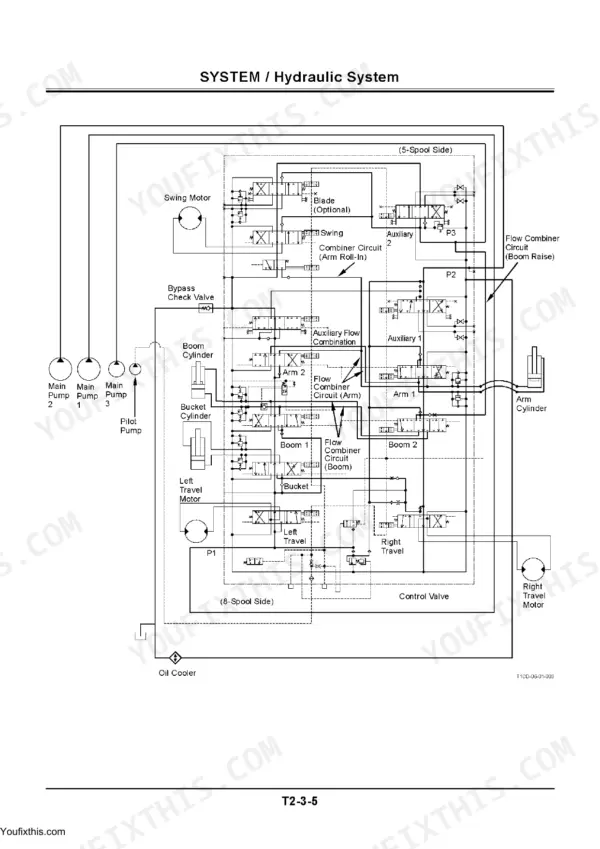
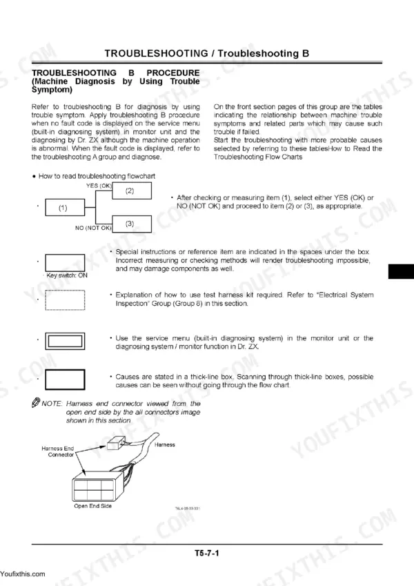
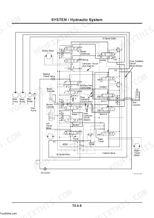
This 638-page Hitachi Technical Manual covers the ZX70-3, ZX70LC-3, ZX70LCN-3, ZX75US-3 and ZX85US-3 excavators. The technical volume (p7-230) explains the machine system by system, from the controllers and control system through the pump, swing and travel devices. The troubleshooting volume (p231-638) gives you the performance tests with their standard values, the Monitor Unit and Dr. ZX diagnostic procedures, the ICF data lists, the full MC and engine fault-code tables, symptom-based troubleshooting, and the electrical system inspection with its circuit diagrams.
What's Inside This Manual
| System | Pages | Key Topics |
|---|---|---|
| Technical Manual: Introduction & Scope | 1-6 | To the Reader, Additional References, Manual Composition, Page and Section Numbering, Safety |
| General | 7-40 | Group 1 Specifications, Group 2 Component Layout |
| System | 41-132 | Group 1 Controller, Group 2 Control System, Group 3 Hydraulic System |
| Component Operation | 133-230 | Group 1 Pump Device, Group 2 Swing Device, Group 3 Control Valve, Group 4 Pilot Valve, Group 5 Travel Device, Group 6 Others |
| Troubleshooting Manual: Introduction & Safety | 231-272 | To the Reader, Manual Composition, Safety Precautions, Avoid Injury From Rollaway Accidents, Service Manual Revision Request |
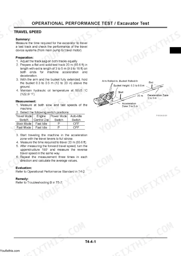
| Performance Test | 273-354 | Group 1 Introduction, Group 2 Standard, Group 3 Engine Test, Group 4 Excavator Test, Group 5 Component Test |
| Troubleshooting: Section Contents | 355-357 | Group Index, Diagnosing Procedure, Monitor Unit, Dr. Zx, Icf, Component Layout, Troubleshooting a and B, Electrical System Inspection |
| Diagnosing Procedure | 358-362 | Introduction, Fault Confirmation, Machine Data Collection |
| Monitor Unit | 363-412 | Outline, How to Use Screens, When an Alarm Is Issued, Contents of Alarms, Time and Maintenance Setting, Monitoring, Service Menu (Built-In Diagnosing System), Controller Version, Keyless Hour Meter |
| Dr. Zx Diagnostic Tool | 413-426 | Outline, Monitoring List, Mc Setup, All Parameter Adjustment, Fault Code Reading, Data Recording |
| Icf (Information Controller) | 427-450 | Outline, List of Daily Report Data, Frequency Distribution Data, Total Operating Hours, Download and Upload of Icf Data, Satellite Communication System, List of Fault Codes |
| Component Layout | 451-466 | Main Component Layout, Electrical System Overview, Monitor and Switches, Controllers and Relays, Engine, Pump Device, Battery, Control Valve, Swing and Travel Devices |
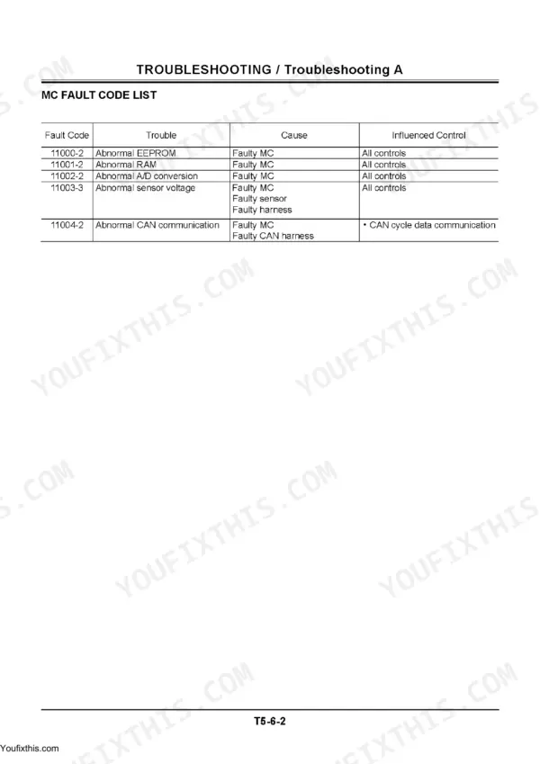
| Troubleshooting a (Fault Codes) | 467-530 | Troubleshooting a Procedure, Mc Fault Code List, Engine Fault Codes, Icf Fault Codes, Corrective Actions |
| Troubleshooting B (Symptom-Based) | 531-616 | Troubleshooting B Procedure, Relationship Between Symptom and Faulty Part, Engine, Hydraulic, Swing, Travel and Electrical Symptoms |
| Electrical System Inspection | 617-638 | Sensor and Switch Inspection, Solenoid Valve Inspection, Controller Connector Inspection, Harness Continuity Checks, Electrical Circuit Diagrams |
Quick Reference Specifications
| Specification | Value | Page |
|---|---|---|
| Injection Pressure (1st stage) | 16.7 MPa (170 kgf/cm², 2430 psi) | p. 30 |
| Injection Pressure (2nd stage) | 25.0 MPa (255 kgf/cm², 3630 psi) | p. 30 |
| Motor Voltage/Output | 24 V/3.2 kW | p. 29 |
| Fuel Filter | ISUZU 89717254901 | p. 37 |
| Full Flow Filter | β10 > 3.0 | p. 37 |
| Suction Filter | 177 μm (80 mesh) | p. 37 |
| STARTER RELAY Voltage/Current | 24 V | p. 37 |
| Change interval | 500 hours | p. 411 |
| Engine Rated Output | 40.5 kW/2000 min⁻¹ (55 PS/2000 rpm) | p. 29 |