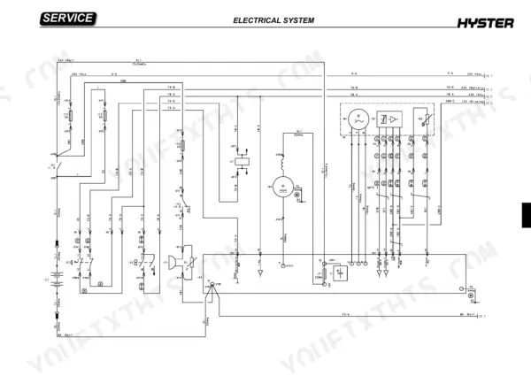
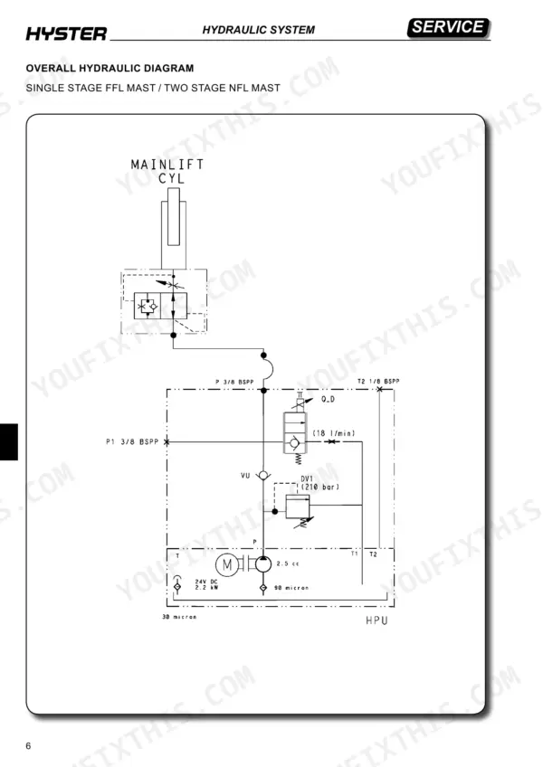
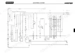
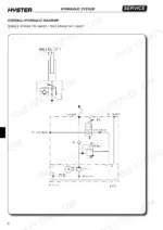
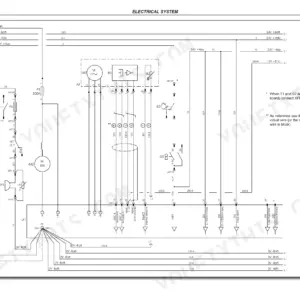
Hyster's 241-page S1.0E service manual PDF (OEM ID 4197722) takes the S1.0E, S1.2E and S2.4HBE tiller forklifts from battery installation and voltage setting through mast chain replacement and electromagnetic brake adjustment. Wiring diagrams trace the tiller board, module connectors and battery charger circuits, while hydraulic schematics lay out the lift pump, pressure control valves and directional valves. Diagnosis gets its own chapter. The Tester menu and alarm troubleshooting tables sit next to electrical component measurements and motor insulation checks. Measure the solenoid valve coil against its 5.6 Ohm figure and the electromagnetic brake coil against 15 Ohm. If your job is renewing a hydraulic pipe or cylinder gaskets, the schematics show how each line connects to the lift pump and valves. A searchable text layer and bookmarked chapters take you straight to the reducer, the drive motor or the scheduled maintenance tables, so you can name the right assembly before ordering.
What's Inside This Manual
| System | Pages | Key Topics |
|---|---|---|
| Technical Information | 1-3 | Truck Models, Service Network, Manual Purpose |
| General Safety Rules | 4-12 | Personal Safety, Workplace Safety, Battery Safety, Suspension Elements, Welding Safety |
| Presentation | 13-23 | Truck Presentation, Views of the Truck, Truck Identification Data and Load Capacities (Truck Identification Data Plate, Load Capacity Data Plate, Truck Punching) |
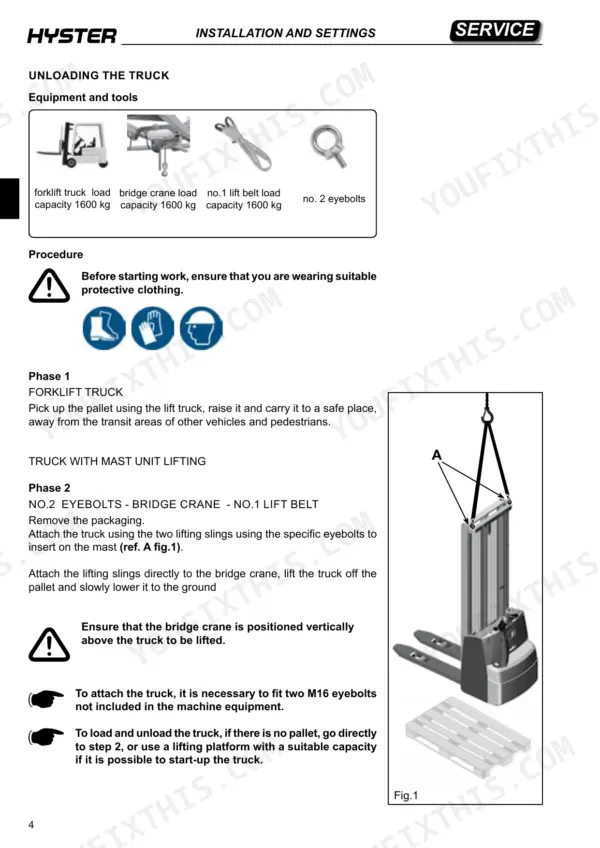
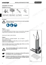
| Installation and Settings | 24-36 | Truck Unloading, Oil Reservoir, Battery Installation, Battery Voltage Setting, Truck Usage Conditions |
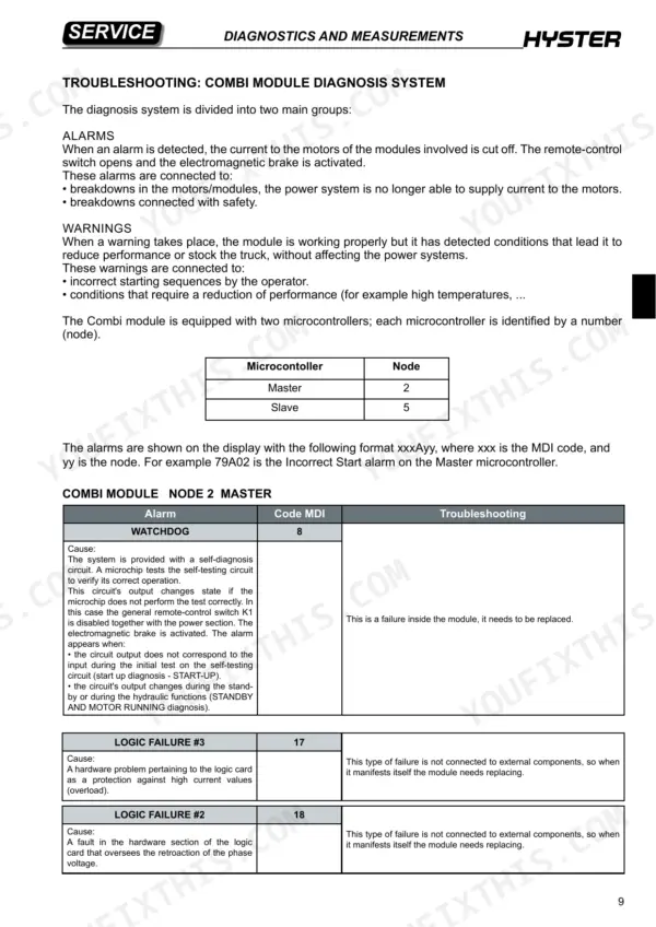
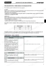
| Diagnostics and Measurements | 37-64 | Module Connectors, Tester Menu, Alarm Troubleshooting, Electrical Component Measurements, Motor Insulation |
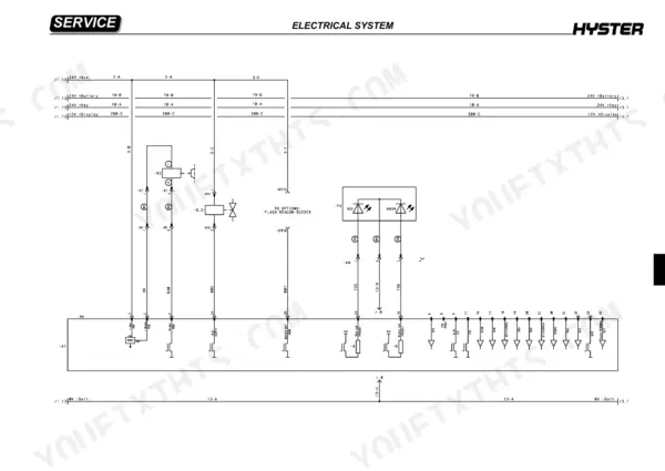
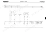
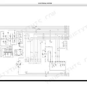
| Electrical System | 65-125 | Wiring Diagrams, Tiller Board, Battery Status Led, Truck Functions, Module Parameters, Battery Charger |
| Hydraulic System | 126-169 | Hydraulic Functions, Pressure Control Valves, Directional Valves, Lift Pump, Hydraulic Pipes, Cylinder Gaskets |
| Basic Truck Mechanics | 170-199 | Traction Wheel, Castor Wheel Assembly, Load Wheels, Tiller, Drive Motor |
| Mast Assembly Mechanics | 200-221 | Mast Characteristics, Mast Assembly Components, Fork Small Mast, Chain Replacement, Bearing Replacement |
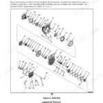
| Reducer | 222-227 | Reduction Unit Components, Reduction Unit Removal, Reduction Unit Disassembly |
| Braking System | 228-233 | Electromagnetic Brake Components, Operation, Braking Systems, Electromagnetic Brake Dismantling, Electromagnetic Brake Adjustment |
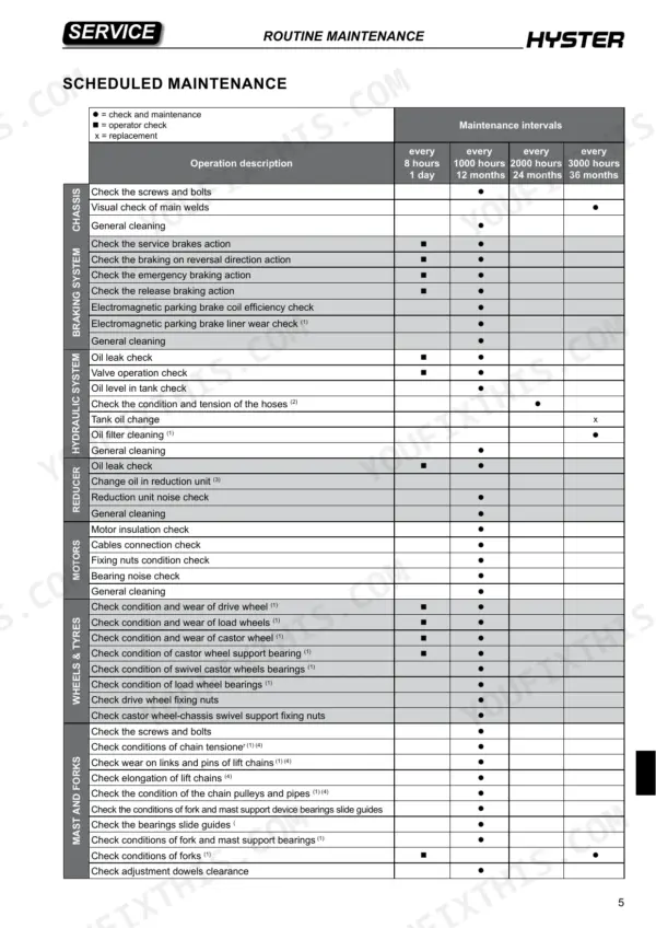
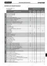
| Routine Maintenance | 234-241 | Warnings, Lubricants, Cleaning Products, Scheduled Maintenance |
Quick Reference Specifications
| Specification | Value | Page |
|---|---|---|
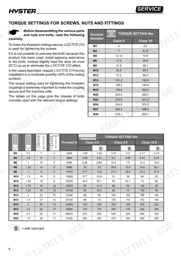
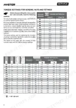
| Torque setting for M3 screw (Class 8) | 4 Nm | p. 8 |
| Torque setting for M3 screw (Class 10) | 5.2 Nm | p. 8 |
| Solenoid valve coil resistance | 5.6 Ohm | p. 63 |
| Electromagnetic brake coil resistance | 15 Ohm | p. 63 |
| Inverter maximum current (24V) | 165A (RMS) for 2' | p. 102 |
| Output direct current (24V) | 70A (RMS) continua. | p. 102 |
| Fixing screws of the Q_D valve torque | 45 Nm | p. 138 |
| Castor wheel screw torque | 60 Nm | p. 177 |
| Castor wheel screw torque | 60 Nm | p. 177 |
| Castor wheel to truck screws torque | 51-56 Nm | p. 177 |
| Maximum air pressure for cleaning | 1 bar | p. 4 |
| Drive motor power (S2 60 minutes) | 1.2 kW | p. 21 |