
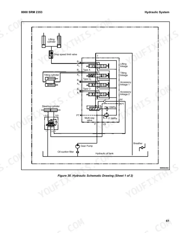
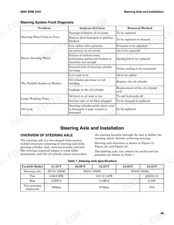
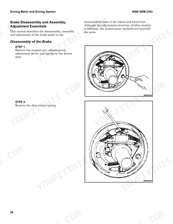
Common Curtis controller fault codes sit in the electrical section of this Hyster J2.5UT service manual PDF, a 94-page reference (OEM ID 8000 SRM 2353) for five J UT series battery forklift trucks, J1.5UT through J3.5UT. A wiring diagram lays out the electrical system around the AC motor controller, while hydraulic schematics trace oil flow through the gear pump, multi-way valve, full hydraulic orbitrol and speed limit valve. Fault diagnosis sections follow the gear pump, multi-way valve, steering system and brakes, and the lifting chapter takes in mast installation and disassembly, fork carriage height adjustment and lift and tilt cylinder work. Your J2.0UT or J2.5UT runs a 600Ah standard battery; when setting wheel bearing preload, take the slot nut to 206 to 235 N•m first, then finish at 9.8 N•m. Ordering seals or a microswitch? Check the List of Wear Parts. Bookmarked and text-searchable, the PDF lets you finish that preload adjustment to the book's own figures.
What's Inside This Hyster J1.5UT–J3.5UT Manual
| System | Pages | Key Topics |
|---|---|---|
| Forklift Truck Main Parts | 7-11 | Battery and Installation, Use of Battery |
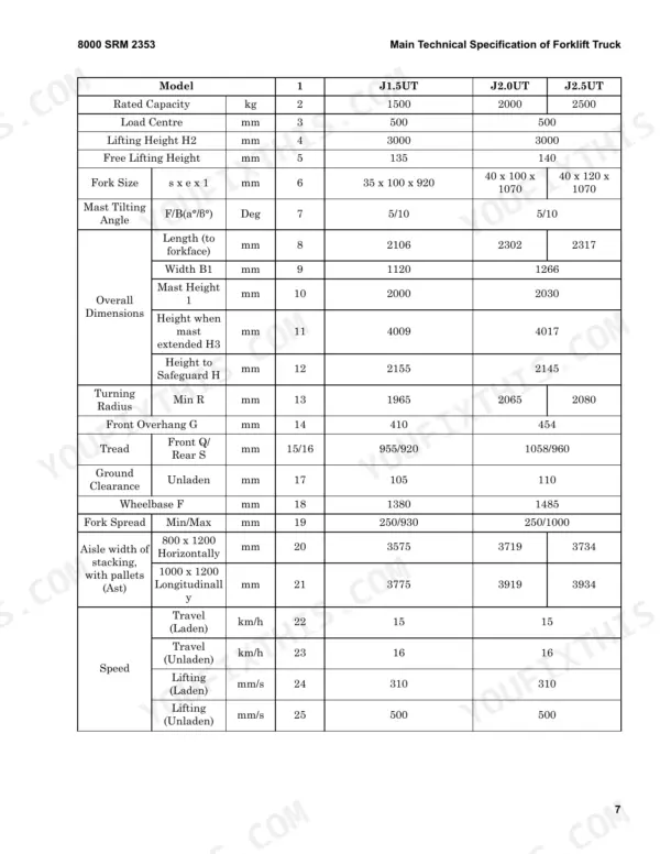
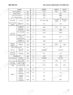
| Main Technical Specification of Forklift Truck | 12-15 | Rated Capacity, Load Centre, Lifting Height, Mast Tilting Angle, Turning Radius, Travel Speed |
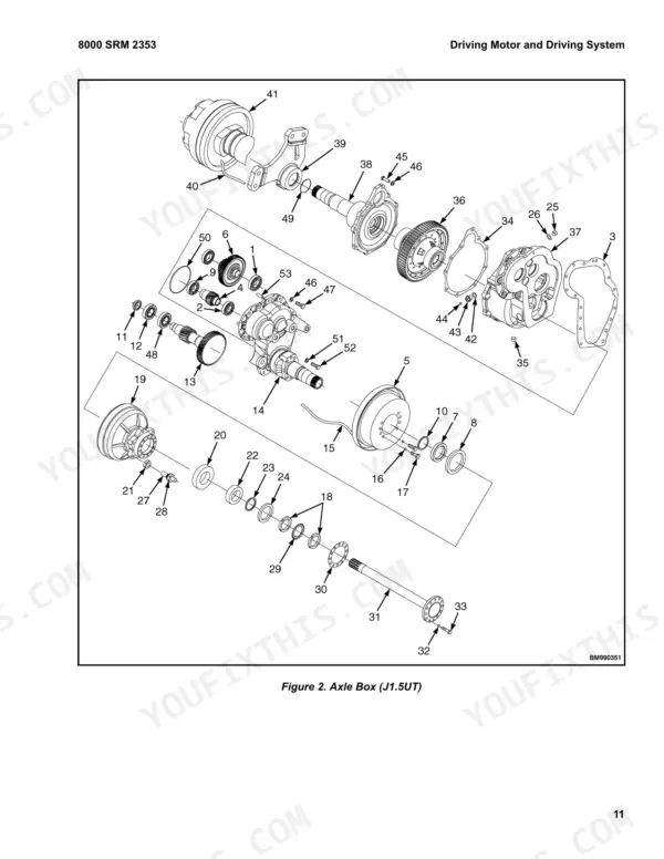
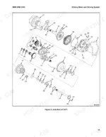
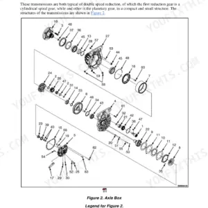
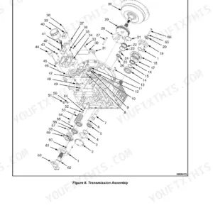
| Driving Motor and Driving System | 16-33 | Overview, Axle Box and Differential (Notes for Installation and Use, Front Tyre and Wheel Rim Models, Installation of Wheel Hub) |
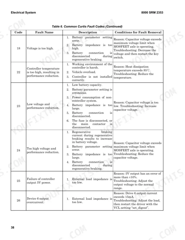
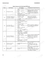
| Electrical System | 34-53 | Overview, Common Curtis Fault Codes |
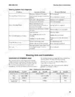
| Steering Device and Installation | 54 | Overview (Steering System: After Reassembly, Fault Diagnosis) |
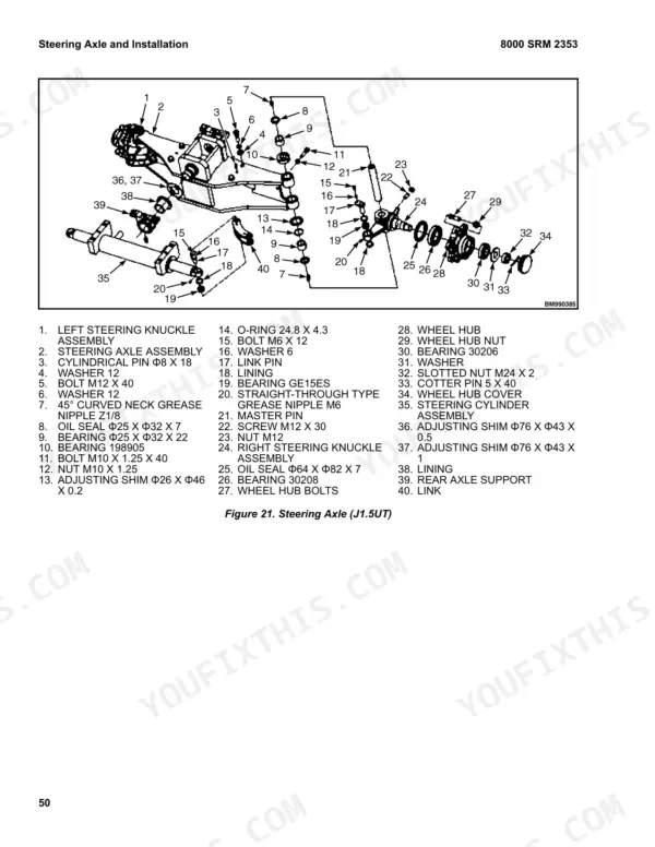
| Steering Axle and Installation | 55 | Overview of Steering Axle (Essentials of Adjustment and Maintenance, Steering Wheel Bearing Preload Adjustment) |
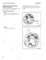
| Parking Brake Operation | 56-64 | Overview (Operating Device of the Parking Brake) |
| Hydraulic Oil Tank and Installation | 65 | Overview, Hydraulic Oil Tank |
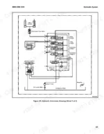
| Hydraulic System | 66-79 | Overview, Gear Pump (Maintenance of Gear Pump, Fault Diagnosis), Multi-Way Valve (Fault Diagnosis), Full Hydraulic Orbitrol, Speed Limit Valve, Hydraulic Pipeline |
| Lifting System | 80-90 | Safety Procedures When Working Near Mast, Overview, Inner and Outer Mast, Fork Carriage Assembly (Adjustment for Height of Fork Carriage), Roller Positions (Fork Backrest) |
| List of Wear Parts | 91-94 | Paper Cushion, Oil Seal, Seal Ring, Retainer Ring, O-Seal Ring, Microswitch |
Quick Reference Specifications
| Specification | Value | Page |
|---|---|---|
| All Models | ||
| Wheel bearing slot nut torque (initial) | 206 to 235 N•m (151.9 to 173.3 lbf ft) | p. 61 |
| Wheel bearing slot nut torque (final) | 9.8 N•m (7.2 lbf ft) | p. 61 |
| Pinion assembly nut tightening torque | 3.0 - 3.5 N·m | p. 23 |
| Wheel hub bearing grease amount | 130 to 190 ml | p. 23 |
| Wheel hub bearing installation torque | 10 - 30 N·m | p. 23 |
| Axle box screw plug tightening torque | 45 - 60 N·m | p. 23 |
| Wheel hub starting torque | 5 - 15 N·m | p. 23 |
| Steering wheel bearing preload adjustment torque (initial) | 206 to 235 N·m | p. 61 |
| Steering wheel bearing rotational torque | 2.94 ~ 7.8 N·m | p. 61 |
| J1.5UT | ||
| Battery Capacity (Standard) | 420Ah | p. 7 |
| J2.0UT, J2.5UT | ||
| Battery Capacity (Standard) | 600Ah | p. 7 |
| J3.0UT, J3.5UT | ||
| Battery Capacity (Standard) | 500Ah | p. 7 |
Hyster J1.5UT–J3.5UT Common Problems This Manual Covers
Hyster J1.5UT to J3.5UT Curtis code 47 high pedal protection or operation sequence failure at startup
Stop operation as soon as the code appears and keep the truck parked until the fault is cleared, as the caution on page 43 requires. Check the key switch, interlock, direction and accelerator inputs and their wiring following page 48. Then re-enter the inputs in the correct startup order. If code 47 follows an emergency reverse, reset the accelerator, forward/reverse and interlock inputs before restarting.
Manual Section: Electrical System Fault Diagnosis p. 48Curtis code 17 or code 23 low voltage fault and reduced truck performance
Stop operation when the code appears, and charge the battery as soon as the display reads below 20%, per page 43. Check battery capacity and the battery parameter settings following page 44. Inspect the battery connection, the fuse and the main contactor for a disconnect. Check for excessive battery impedance and for power draw from non-controller systems before restarting.
Manual Section: Electrical System Fault Diagnosis p. 44Curtis code 39 main contactor not closed, capacitor voltage fails to reach B+ voltage
Inspect the main contactor contacts for oxidation, melting or an unstable connection following page 46. Check the fuse for a disconnect and verify that no external device is charging the capacitor. Check the contactor, then restart the key switch and confirm the code clears. Do not operate the truck while the code is active, per the caution on page 43.
Manual Section: Electrical System Fault Diagnosis p. 46Curtis code 16 or 22 controller temperature too high with reduced performance
Check the controller working environment, vehicle load and controller installation following page 44. Code 22 sets when heat dissipation temperature exceeds 85°C. Code 16 sets above 95°C, per page 43. Stop operation while the code is active. Reduce the load, let the controller cool below the limit, then restart the key switch or interlock switch.
Manual Section: Electrical System Fault Diagnosis p. 44Battery capacity drops at normal discharge with quick voltage drop and low specific gravity
Check for pole plate salinization following page 10. Look for these causes: a low electrolyte level exposing the plate tops, high electrolyte proportion, impure electrolyte, long storage in a discharged state, or long-term undercharging. Recover the cells with the overcharging, repeated charging or hydropathy method. Follow the warning on page 11: work to the Battery Use and Maintenance Manual and contact a professional with any questions.
Manual Section: Battery Common Failures and Disposal Methods p. 10Gear pump pressure low, small oil drainage quantity, or noise present during operation
Test the gear pump following page 71. Hold pump speed at 1500 to 2000 rpm and raise pressure 20 to 30 kg/cm² at a time. Run 5 minutes per step until pressure reaches 175 kg/cm². Monitor oil temperature, pump surface temperature and running sound throughout. If either temperature runs too high, reduce the load and let the oil cool before continuing.
Manual Section: Hydraulic System Gear Pump Fault Diagnosis p. 71Frequently Asked Questions
How do I reset error codes on a Hyster J1.5UT, J2.0UT, J2.5UT, J3.0UT, or J3.5UT?
For most Curtis controller fault codes, the condition for fault removal is to restart the key switch. For specific faults like code 14 (Pre-charging failure), you must re-input via VCL reset or interlock switch, and for code 26 (Device 6 output overcurrent), you must restart the driver with the VCL setting 'set_digout'. p. 43
Why will a Hyster J1.5-3.5UT not move or lift?
If the forklift cannot move forward or backward and the hydraulic lifting part also fails, check that the seat switch is normal and ensure the general power supply fuse is not burned out. If the vehicle has no power when starting, verify the fuse status as described on page 53. p. 53
What is the correct wheel hub nut torque for bearing adjustment on the Hyster J1.5UT, J2.0UT, J2.5UT, J3.0UT, J3.5UT?
When adjusting the steering wheel bearing, first tighten the slot nut to a torque of 206 to 235 N•m (151.9 to 173.3 lbf ft), then loosen it and retighten to 9.8 N•m (7.2 lbf ft). p. 61
What is the specified thickness for the lining plate in the gear pump on the Hyster J1.5UT, J2.0UT, J2.5UT, J3.0UT, J3.5UT?
The lining plate in the gear pump must be replaced if the surface is damaged or if its thickness is smaller than the specified value of 4.94mm. p. 69
How do I adjust the multi-way valve safety valve pressure on the Hyster J1.5UT, J2.0UT, J2.5UT, J3.0UT, J3.5UT?
To adjust the safety valve pressure, screw off the measurement hole screw plug on the inlet part of the multi-way valve and mount an oil pressure gauge capable of measuring 20MPa. Operate the tilting handle to the end of its stroke, then loosen the lock nut of the overflow valve and adjust the turning screw until the specified pressure is reached. p. 76
Is this Hyster J1.5UT manual a download or a disc?
All 94 pages arrive as one searchable PDF at checkout. Read it at the desk, then take the phone out to the machine.
Am I free to print this Hyster J1.5UT Service Manual?
Yes. Print individual pages or full chapters for your own shop use, on letter or A4 paper.


Reviews
There are no reviews yet.