
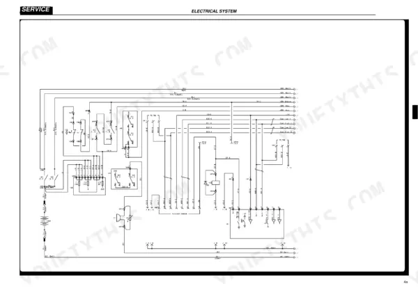
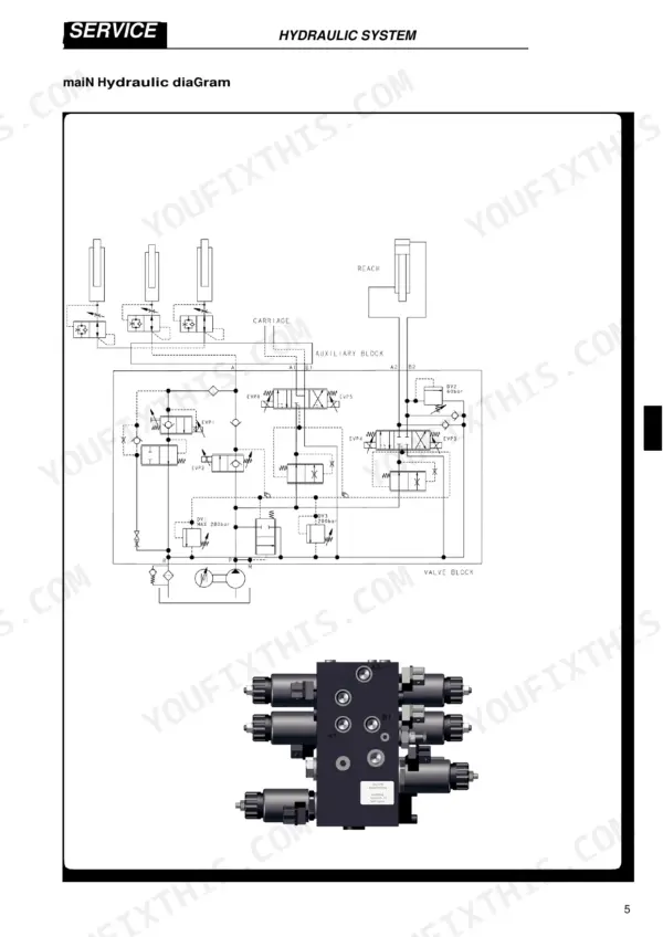
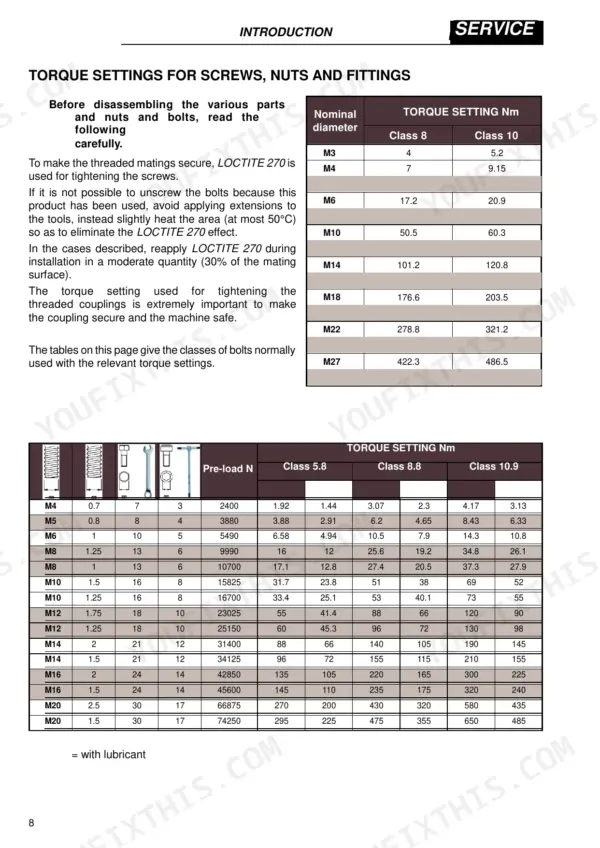
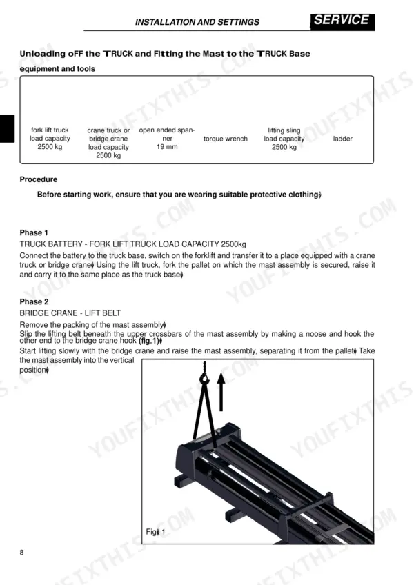
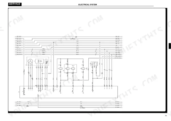
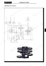
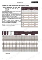
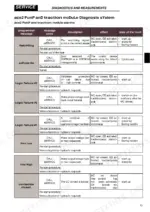
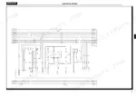
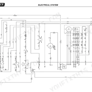
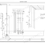
Issued by Hyster under document number 2324864, this 474-page factory book is the Hyster R1.4 service manual PDF for the R series retractable truck, covering seven variants from the R1.4 through the R2.0HD. Wiring diagrams back up the diagnostics for the ACE2 traction, ACE2 pump, EPS ACW and VCM modules, while the hydraulic diagrams trace the solenoid valves, distributor, pressure relief valve, cylinders and lift pump. Replacement procedures run from encoders, contactors and fuses through mast chains, reduction unit removal and both electromagnetic brakes, ending with scheduled maintenance and lubricant data. Confirm your traction motor against its 6.4 kW S2 60-minute rating, and tighten an M12x1.5 revolving female hydraulic fitting to 15-25 Nm. When the display shows a warning or alarm screen, Breakdown Search and the module connector checks are where you start tracing it. Bookmarks and a live text layer keep it quick to search. The pages also print cleanly as a working copy.
What's Inside This Hyster R1.4–R2.5 Manual
| System | Pages | Key Topics |
|---|---|---|
| Technical Information | 1 | Truck Presentation, Load Identification Data, Truck Identification Data Plate, Residual Load Plate, General Specifications |
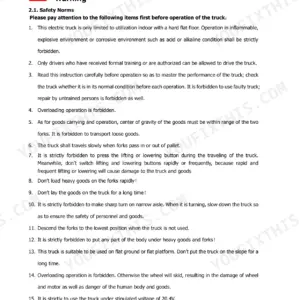
| Introduction | 2-12 | General Safety Rules |
| Presentation | 13-24 | Truck Presentation, Views of the Truck |
| Installation and Settings | 25-44 | Truck Assembly, Battery Installation, Moving Forks Assembly, Load Rack Assembly, Contrasting Roller Assembly, ACE2 Module Settings |
| Diagnostics and Measurements | 45-108 | Module Connectors, ACE2 Traction Module, ACE2 Pump Module, EPS ACW Module, VCM Module, Breakdown Search |
| Electrical System Controls and Standard Display | 109-137 | Armrest Controls, Pedal Unit, Standard Display Keypad, Display Icons, Graphic Screens |
| Premium Display and Truck Functions | 138-169 | Premium Display Icons, Graphic Screens, Energy Saving Function, Warning/Alarm Screens, Combined Hydraulic Functions |
| Menu Navigation and Parameter Settings | 170-212 | Main Menu 1, Main Menu 2, Access Codes, PIN Code Programming, Height Pre-Selector |
| Electrical System Configuration and Modules | 213-277 | Pre-Selector Configuration, Software Updates, Module Parameters, VCM Module, ACE2 Traction Module, EPS ACW Module |
| Electrical Component Replacement and Maintenance | 278-329 | Module Replacement, Encoder Replacement, Horn Replacement, Contactor Replacement, Fuse Replacement, Fan Replacement |
| Hydraulic System | 330-385 | Hydraulic Diagrams, Solenoid Valves, Distributor, Pressure Relief Valve, Cylinders, Lift Pump |
| Truck Base Mechanics | 386-411 | Traction Wheel, Load Wheel, Battery Block, Traction Motor, Steering Motor, Retractable Carriage |
| Mast Assembly Mechanics | 412-432 | Mast Assembly Components, Bearing Replacement, Chains, Chain Tensioner, Chain Sheaves, Cylinder Chain Sheave |
| Small Fork Mast Mechanics | 433-438 | Fork Carriage Components, Fork Carriage Removal, Sliding Blocks Removal, Bearing Replacement |
| Reduction Gear | 439-448 | Reduction Unit Components, Reduction Unit Removal, Traction Motor Drive Shaft O-Ring, Wheel Shaft O-Ring, Reduction Unit Oil |
| Braking System | 449-456 | Traction Motor Electromagnetic Brake, Load Wheel Electromagnetic Brake, Brake Disk, Brake Plate, Electromagnet, Brake Regulator |
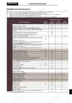
| Routine Maintenance | 457-474 | Oils and Lubricants, Cleaning Products, Scheduled Maintenance, Outriggers, Screws and Bolts, Chains |
Quick Reference Specifications
| Specification | Value | Page |
|---|---|---|
| M3 Class 8 Torque | 4 Nm | p. 8 |
| M3 Class 10 Torque | 5.2 Nm | p. 8 |
| Metric Revolving Female M12x1.5 Torque | 15-25 Nm | p. 9 |
| Metric Revolving Female M14x1.5 Torque | 30-45 Nm | p. 9 |
| traction motor, power S2 60 minutes | 6.4 kW | p. 19 |
| Battery charge level check (speed reduction) | 24% of the maximum speed | p. 286 |
| Battery charge level check (maximum current reduction) | 50% | p. 286 |
| Fuse F3 rating | 2a | p. 311 |
| Fuse F1 rating | 10a | p. 311 |
| Torque for nuts securing the mast assembly to the truck base | 300-330 Nm | p. 425 |
| Torque for screws fastening both side blocks of the mast assembly | 88-97 Nm | p. 425 |
| Upper sliding block wear limit | less than 4.5mm | p. 437 |
Hyster R1.4–R2.5 Common Problems This Manual Covers
Hyster R1.6 traction module shows Battery Low alarm with halved maximum current and reduced travel speed
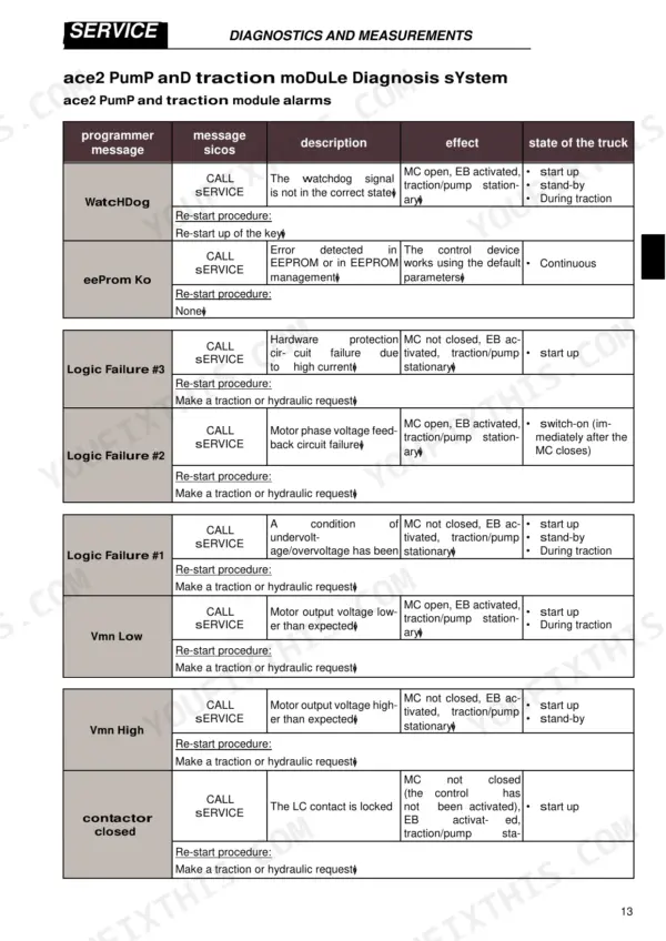
Recharge the battery, then cycle the key to clear the alarm, following the restart procedure on page 58. The alarm sets at 10% charge or less when the BATTERY CHECK parameter is above zero. Never check the charge by bridging terminals with metal jumpers (page 5), and keep tools off the battery top to avoid a short (page 458).
Manual Section: Traction and Pump Module Alarms p. 58Contactor Open alarm with MC coil energized but MC failing to close, truck stationary
Make a traction or hydraulic request to run the restart procedure on page 58. If the alarm returns, disconnect the battery (page 5) and discharge the capacitors in the control unit before working in the electric compartment, as page 458 warns. Inspect the contactor, but never file or lubricate its contacts (page 458); they can stick and cause loss of control. Replace it using the Contactor Replacement procedure.
Manual Section: Traction and Pump Module Alarms p. 58Traction controller Motor Temperat or TH Protection alarm with reduced current and travel speed
Check the motor temperature sensor first: page 58 sets Motor Temperat when a digital sensor reads open or an analogue sensor passes 150°C. TH Protection means the controller reached 85°C and is ramping current down toward 0A at 105°C. Sens Mot Temp Ko on page 61 flags sensor output outside limits. Motor and hydraulic parts stay hot right after shutdown, so wear PPE (page 458).
Manual Section: Traction and Pump Module Alarms p. 58Vacc Out Range or Throttle Prog alarm with traction and pump motor stationary
Verify the accelerator input sits inside the Vacc_min to Vacc_max range acquired with the PROGRAMM VACC function, page 62, then make a traction or hydraulic request to restart. Throttle Prog on page 64 means a potentiometer was not programmed correctly; confirm its programming and cycle the key. If Incorrect Start Pedal appears, release the pedal and make a new traction request (page 63).
Manual Section: Traction and Pump Module Alarms p. 62EPS steering alarm when encoder count and toggle switch sector count do not match
Inspect the steering encoder channels for interference: page 98 shows the steer angle can slip, even with the truck stationary, when sector count and encoder count disagree in the feedback redundancy test. Disconnect the battery before opening any encoder connection (page 5). If SELFCHECK #2 appears, turn the key back on to clear it (page 94); that routine monitors the encoder and motor current at 25Hz.
Manual Section: EPS ACW Module Alarms p. 98Check Up Needed warning followed by travel speed reduction and then traction block
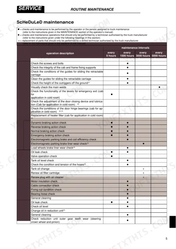
Perform the scheduled maintenance in the Routine Maintenance schedule on page 461 before the counter escalates. Page 256 explains that skipping the programmed maintenance control first cuts speed, then blocks traction. Verify the check up settings on page 287, which list the alarm at 300 hours, speed reduction at 340 hours and truck block at 380 hours.
Manual Section: Electrical System Configuration and Modules p. 256Frequently Asked Questions
What's the torque setting for the mast assembly to truck base on a Hyster R1.4, R1.6, R1.6n, R2.0, R2.5, R1.6HD, R2.0HD?
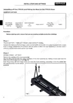
When installing the mast assembly to the truck base, the bolts securing the mast assembly to the truck base (ref.D fig.4) must be tightened to a torque of 300 to 330 Nm. p. 33
How do I perform a reset of the hourmeter for maintenance?
Once the programmed maintenance is performed, you must set the parameter 'check up done' to ON using the programmer to reset the maintenance hourmeter. p. 256
What's the correct torque for the drive wheel retaining nuts on a Hyster R1.4, R1.6, R1.6n, R2.0, R2.5, R1.6HD, R2.0HD?
The traction wheel retaining nuts must be tightened using a torque wrench to a torque of 130 Nm. p. 389
What's the torque for reduction unit housing cover screws on Hyster R1.4, R1.6, R1.6n, R2.0, R2.5, R1.6HD, R2.0HD?
The screws securing the reduction unit to the plate must be tightened using a torque wrench to a torque of 88 Nm. p. 443
What is the procedure for bleeding the lifting cylinder?
Raise the forks with no load by approximately 300mm, stop and wait for 10 seconds, and repeat this process until all air has come out of the bleed valve. Finally, take the forks to full height and tighten the screw (ref.B fig.1) on page 368. p. 368
Is this Hyster R1.4 manual a PDF I download?
One searchable PDF covering 474 pages, delivered instantly. No disc, no shipping, no waiting on the post.
Am I able to print pages from this Hyster R1.4 manual?
Yes. Print individual pages or full chapters for your own shop use, on letter or A4 paper.


Reviews
There are no reviews yet.