


![John Deere 5415 5415N 5415H 5615 5615HC 5715 5715HC Repair Manual [Tractor]](https://youfixthis.com/wp-content/uploads/2012/02/Manual_Download-300x300.jpg)
Part of the John Deere Repair Manuals.
This is the complete John Deere factory repair manual (TM4559) for the 6010, 6110, 6210, 6310, 6410, 6510 and 6610 tractors, including SE-series variants. Across 2,266 pages it covers every major system on these mid-range 4-cylinder machines: rebuilding the naturally aspirated and turbocharged diesel engines, servicing all four transmission families fitted to this range (SyncroPlus, Power Reverser, AutoPowr and PowrQuad/AutoQuad), diagnosing and repairing the hydraulic system, front-wheel drive and final drives, tracing wiring faults through the full harness diagrams, and servicing the operator cab and ROPS structure. It is the same information a John Deere dealer technician uses, with torque values, capacities and test pressures called out at every step.
What's Inside This John Deere 6010-6610 Repair Manual
| System | Pages | Key Topics |
|---|---|---|
| Safety | - | |
| General Information | Specifications, Tune-Up, Predelivery Inspection, Torque Values | |
| Engine | Engine Removal and Installation, Lower Engine Repair, Seals and Gaskets | |
| Fuel, Air Intake, Cooling and Exhaust Systems | Speed Control Linkage, Fuel System, Air Intake System, Cooling System, Cold-Weather Starting Aids, Exhaust System | |
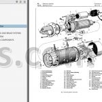
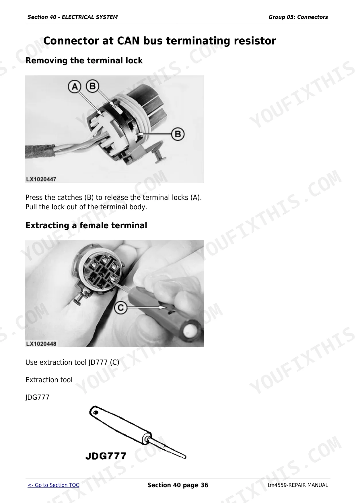
| Electrical System | Connectors, Wiring Harnesses, Charging Circuit, Starting Motor Circuit, Fuses and Relays, Monitoring Systems, Electrical Components | |
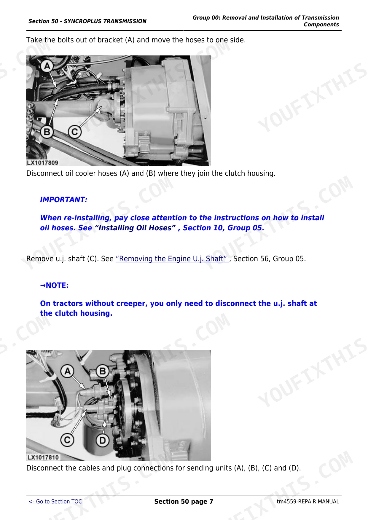
| SyncroPlus Transmission | Removal and Installation, Shift Controls, Perma Clutch Ii, Gear Transmission | |
| Power Reverser | Removal and Installation of Power Reverser Module, Shift Controls, Power Reverser Module Repair, Gear Transmission | |
| AutoPowr Transmission | Removing and Installing AutoPowr Transmission, Shift Controls, Input Housing, Output Housing, Differential Drive Shaft Assembly | |
| PowrQuad and AutoQuad Transmissions | Removal and Installation, Shift Controls, PowrQuad Module, Creeper Transmission, Option Transmission, Range Transmission | |
| Drive Systems | U-Jointed Shafts and Torsion Damper, Front-Wheel Drive Clutch, Differential, Hydraulic Pump Drive, Final Drives, Rear PTO, Front PTO, Front Implement Drive | |
| Steering and Brakes | Hydrostatic Steering, Steering Cylinders, Brake Valve (Non-Power), Brake Valve (Power Fill), Brake Valve (MFWD/Disk), Rear Brakes, Handbrake, Air Brakes | |
| Hydraulic System | Hydraulic Controls, Hydraulic Pump and Charge Pump (Pfc), Valves, Cylinders and Actuators | |
| Miscellaneous | Cab Mounts, Ballast, Tires and Wheels | |
| Operator Cab and 2-Post ROPS | Cab Structure, Operator Station Components, ROPS Assembly | |
| Special Tools | Dealer-Fabricated Tools, Fabrication Drawings |
Quick Reference Specifications
| Specification | Value | Page |
|---|---|---|
| 6010, 6510, SE 6010, SE 6510 | ||
| Engine configuration - 6010 and 6510 | 4-cylinder naturally aspirated diesel | |
| 6110, 6210, 6310, 6410, 6610, SE 6110, SE 6210, SE 6310, SE 6410, SE 6610 | ||
| Engine configuration - 6110, 6210, 6310, 6410, 6610 | 4-cylinder turbocharged diesel | |
| General Fasteners - All Models | ||
| M6 Class 4.8 Bolt Torque (lubricated) | 4.7 N.m (3.5 lb-ft) | |
| M6 Class 4.8 Bolt Torque (dry) | 6 N.m (4.4 lb-ft) | |
| M6 Class 8.8/9.8 Bolt Torque (lubricated) | 9 N.m (6.6 lb-ft) | |
| M6 Class 8.8/9.8 Bolt Torque (dry) | 11.5 N.m (8.5 lb-ft) | |
| 6010, 6110, 6210, 6310, 6410, 6510, 6610 and SE variants | ||
| Production Years | 1998-2004 | |
John Deere 6010-6610 Common Problems This Manual Covers
Hydraulic pump internal bearing and snap ring failure causing complete hydraulic system loss
This failure costs $7,000-8,000 to repair at a dealer. The Hydraulic System section covers removing the hydraulic pump and charge pump assembly, inspecting bearings and snap rings for wear or fracture, and replacing seals and internal components. Catch it early by monitoring for unusual noise from the pump and checking hydraulic oil for metal contamination at each service interval.
Manual Section: Hydraulic SystemSteering becomes heavy and all hydraulic loader and implement functions stop simultaneously
Simultaneous loss of steering assist and loader hydraulics points to the main hydraulic pump or a completely blocked intake screen. The Hydraulic System section covers removing and testing the pump and charge pump, cleaning the intake screen and inspecting the PFC control valve. Check the oil level and filter condition first before condemning the pump, as low oil is a common contributing factor.
Manual Section: Hydraulic SystemEngine fails to start - no crank or slow crank with no fault codes present
Starting failures on these tractors are commonly traced to a weak battery, a faulty starter motor or corroded ground connections at the engine block. The Electrical System section covers testing the starting motor circuit, battery load testing, and locating the main ground points and harness connectors so you can isolate the fault without replacing parts at random.
Manual Section: Electrical SystemThird-function valve (grapple/joystick) shows no pressure output and grapple will not move
No pressure from the third-function circuit with joystick movement indicates a stuck spool, a failed solenoid valve or incorrect power-beyond plumbing. The Hydraulic System section covers testing and cleaning the solenoid valve, inspecting the spool for contamination and verifying the power-beyond port connections so the correct downstream pressure is restored to the grapple circuit.
Manual Section: Hydraulic SystemFrequently Asked Questions
Which transmission types are covered in the John Deere 6010-6610 repair manual?
This manual covers all four transmission families fitted to the 6010-6610 range: the SyncroPlus gear transmission, the Power Reverser shuttle module, the AutoPowr continuously variable (IVT) transmission and the PowrQuad/AutoQuad powershift. Each has its own chapter with full removal, disassembly and rebuild procedures.
How do I diagnose hydraulic steering failure on a John Deere 6610?
Heavy steering combined with loss of hydraulic functions usually points to the hydraulic pump or a blocked intake screen starving the PFC system. The Hydraulic System section covers testing the pump and charge pump output, inspecting the control valves and clearing the intake. Check that oil level and condition are correct before pulling the pump.
What does BCU 131 error code mean on a 6010-6610 tractor?
BCU 131 indicates a fault in the turn signal bulb circuit or the associated wiring harness. The Electrical System section covers the body control unit circuit, connector and harness locations, and the test procedure for the turn signal circuit so you can isolate whether the fault is a blown bulb, a broken wire, or a connector corrosion issue.
Does this manual cover the AutoPowr IVT transmission on 6010-6610 tractors?
Yes. Section 53 (AutoPowr Transmission) covers removing and installing the full transmission, the shift controls, input housing, output housing and differential drive shaft assembly with all required torques and clearances. It applies to 6010-6610 models fitted with the optional AutoPowr continuously variable transmission.
What are the most frequently replaced parts on John Deere 6010-6610 tractors?
Air filters, hydraulic pump seals, control valve components and cylinder rod seals top the service list on these machines. Drive belts, water pump seals and front axle U-joints also see regular replacement. The Drive Systems and Hydraulic System sections list the required part clearances and torques to get each repair done correctly the first time.
How quickly can I access this John Deere 6010, 6110, 6210, 6310, 6410, 6510?
You get a 2266-page searchable PDF (41 MB) that downloads instantly after checkout. Open it on your laptop, tablet, or phone, and bring it right to the shop floor.
Can I print this manual?
Yes, print as many copies as you want, and there are no restrictions. Many mechanics print the section they need and bring it to the shop floor.