
![John Deere 200CLC 230CLC 270CLC Repair Manual [Excavator]](https://youfixthis.com/wp-content/uploads/2012/02/Manual_Download-300x300.jpg)

Part of the John Deere Repair Manuals.
John Deere publication TM6019 for the 5415, 5415N, 5415H, 5615, 5615HC, 5715 and 5715HC tractors - narrow and high-clearance versions included - 1,388 pages. It is two manuals in one binding.
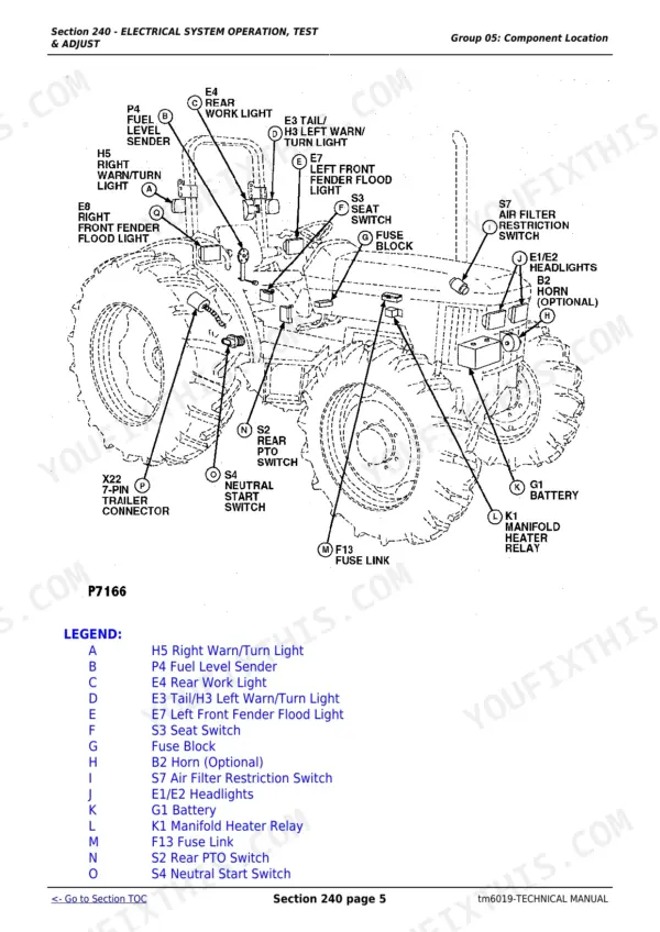
Sections 10 to 90 are the repair half: general information, engine removal and installation, fuel and air, electrical, the whole power train (clutch housing, clutch assembly, LUK clutch, CollarShift and SyncShuttle transmissions, PTO and final drives), steering and brakes, hydraulics, front axles and the operator station. Sections 210 to 290 are the operation, tests and adjustments half that dealers normally sell as a separate book: the operational checkout procedure, component locations, and diagnosis with specifications for engine, fuel and air, electrical, power train, steering and brakes and hydraulics, closing with dealer-fabricated tools.
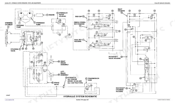
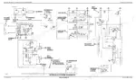
On diagrams, precisely: the hydraulic schematics are here - page 1380 is the full ISO-symbol hydraulic system schematic (drawing LV2267), with legends for tractors with and without selective control valves, a 5415 Narrow variant and a Power Beyond schematic. The electrical section carries component locations, tests, adjustments and the complete schematic legend (components B1 to Y1, connectors X1 to X31), but the wiring schematic SHEETS are not printed in this volume. Engine internals point to CTM104, John Deere's separate component manual.
Complete the set for your 5415-5715 (incl. N and HC)
What's Inside This John Deere 5415-5715 (incl. N and HC) Repair Manual
| System | Pages | Key Topics |
|---|---|---|
| General Information | 1-80 | Safety, Recognize Safety Information, Understand Signal Words, Follow Safety Instructions, Handle Fluids Safely-Avoid Fires, Prevent Battery Explosions |
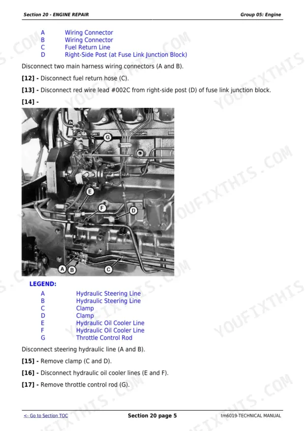
| Engine Repair | 81-114 | John Deere Engine Repair-Use CTM104, Remove Engine, Install Engine, Cooling System, Engine Water Pump Repair-Use CTM104, Remove and Inspect Radiator |
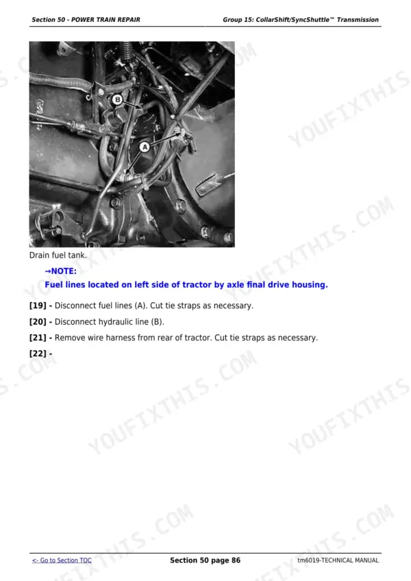
| Fuel and Air Repair | 115-141 | Fuel System, Injection Pump, Nozzle and Governor Repair-Use CTM104, Remove, Inspect and Install Fuel Tank, Replace Fuel Filter, Remove and Install Fuel Filter/Primer Pump Assembly, Remove and Install the Water Separator Assembly |
| Electrical Repair | 142-176 | Battery, Starter and Alternator, Starter Repair-Use CTM77, Remove and Install Battery, Remove and Install Starter, Replace Alternator/Regulator - 40 AMP, Electrical System Components |
| Power Train Repair - Clutch Housing | 177-194 | Other Material, Service Parts Kits, Separate Engine From Clutch Housing, Install Engine to Clutch Housing, Replace Clutch Housing Seal, Inspect and Repair Clutch Pedal and Linkage |
| Power Train Repair - Clutch Assembly | 195-220 | Special or Essential Tools, Tools, PTO Clutch Finger Height Gauge, Traction Clutch Finger Height Gauge, Traction Clutch Finger Height Adjustment Tool, Remove and Install Clutch Assembly |
| Power Train Repair - LUK Clutch Assembly | 221-257 | Essential Tools, Service Equipment and Tools, Specifications, Disassemble and Inspect Clutch Assembly, Assemble Clutch Assembly, Traction Clutch Finger Adjustment |
| Power Train Repair - Collarshift/Syncshuttle™ Transmission | 258-361 | Separate Clutch Housing From Transmission, Install Clutch Housing to Transmission, Inspect and Repair Gear Shift Lever5415, 5615 Y 5715 ( -00, Inspect and Repair Range Shift Lever5415, 5615 Y 5715 ( -0, Inspect and Repair Gear and Range Shift Levers5415 (003592, Remove Transmission |
| Power Train Repair - Troubleshooting, Specifications & Disassembly | 362-579 | Rear PTO Drive Shaft, Inspect and Repair Rear PTO Lever and Linkage, Remove and Install Standard Rear PTO Drive Shaft Assembly, Disassemble, Inspect and Assemble Standard Rear PTO Drive, Inspect and Repair PTO Lever and Linkage 5415 Narrow, Differential |
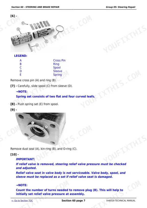
| Steering and Brake Repair | 580-657 | Remove and Install Steering Column and Valve, Disassemble and Inspect Steering Valve, Assemble Steering Valve, Remove and Install Steering Cylinder-2WD Axle, Remove and Install Steering Cylinder-2WD Axle (5415N), Remove and Install Steering Cylinder-2WD Axle (High Cleara |
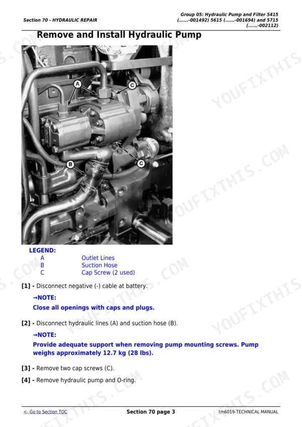
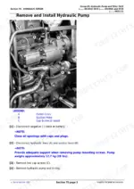
| Hydraulic Repair | 658-762 | Hydraulic Pump and Filter 5415 (......-001492) 5615 (....., Remove, Inspect, And Install Hydraulic Oil Pick-Up Screen, Remove and Install Hydraulic Pump, Remove Hydraulic Pump External Components, Disassemble and Inspect Hydraulic Pump, Assemble Hydraulic Pump |
| Miscellaneous Repair | 763-822 | Front Axle-2WD, Remove and Install Front Axle-2WD, Remove and Install Front Axle-2WD (5415N), Remove and Install Front Axle-2WD (High Clearance Tractors, Inspect and Replace Pivot Pin and Bushings-2WD Axle, Remove and Install Spindle Assembly-2WD Axle |
| Operator Station Repair | 823-842 | Seat and Support, Remove and Install Seat and Support, Control Console and Panel, Remove and Install Right-Side Control Console and Panel, Remove and Install Left-Side Control Console and Panel, Fenders 5415 Narrow |
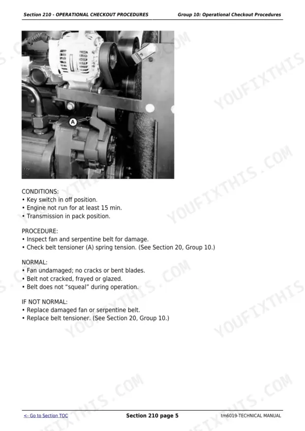
| Operational Checkout Procedures | 843-880 | Operational Checkout Procedure Information, Engine Oil Level and Condition Check, Coolant Level and Condition Check, Transmission and Hydraulic Oil Check, Fan and Serpentine Belt Check, Fuel System Check |
| Engine Operation, Tests, and Adjustments | 881-936 | Component Location, Component Location Information, Engine External Components-Left-Hand Side, Engine External Components-Right-Hand Side, Theory of Operation, Theory of Operation Information |
| Fuel/Air Operation, Tests, and Adjustments | 937-967 | Fuel System Components-5415 SN( - 004530), 5615 Sn( - 0037, Fuel System Components-5415 SN(004531 - ), 5615 SN(003763, Fuel System Components-5415 Narrow, Air Intake System Components-Without Turbocharger, Air Intake System Components-With Turbocharger, Fuel System Operation |
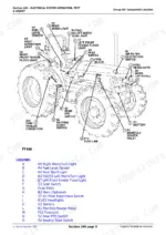
| Electrical System Operation, Test & Adjust | 968-1099 | Engine Electrical Components - 4 Cylinder, Dash Electrical Components, Machine Electrical Components, Machine Electrical Components 5415 Narrow, Fuse Block and Fuses, Relays |
| Power Train Operation, Tests and Adjustments | 1100-1197 | Component Location-Collar Shift/SyncShuttle™ Transmission, Power Train Components-Range Shift Lever at Right Side5415, Power Train Components-Range Shift Lever at Left Side5415, Clutch Components-CollarShift and SyncShuttle™ Transmissio, Transmission Components-CollarShift, Transmission Components-SyncShuttle™ |
| Steering and Brake Operation, Test & Adjust | 1198-1257 | Steering System Components - 5415, Steering System Components -5415 Narrow, Steering System Components - 5615 and 5715-5715HC, Brake System Components, Brake System Components-5415 Narrow, Steering System Operation - 5415 |
| Hydraulic System Operation, Tests, and Adjustments | 1258-1384 | Hydraulic System Components-5415, Hydraulic System Components-5415 Narrow, Hydraulic System Components-5615 and 5715, Selective Control Valve Components, Selective Control Valve Components-5415 Narrow, Hydraulic System Operation |
| Dealer Fabricated Tools | 1385-1388 | DFLV1A Final Drive Turning Tool |
Quick Reference Specifications
| Specification | Value | Page |
|---|---|---|
| PTO power at 2400 rpm | 49.2 kW (66 hp) (5415, 5415N, 5415H) / 52.2 kW (70 hp) (5615) / 57.4 kW (77 hp) (5715) | p. 27 |
| Engine displacement | 4.5 L | p. 27 |
| Hydraulic pump capacity | 85 L/min (22.5 gpm) | p. 28 |
| Fuel tank capacity | 95 L (25 U.S. gal) (standard) / 60 L (16 U.S. gal) (5415N narrow) | p. 28 |
John Deere 5415-5715 (incl. N and HC) Common Problems This Manual Covers
Clutch slipping or pedal engagement point wandering after years of loader work.
The Power Train Repair clutch sections walk through separating the engine from the clutch housing, removing the clutch assembly, and setting finger height with the dedicated gauges - including the separate LUK clutch procedure with its own finger adjustment spec, since these tractors shipped with two clutch designs.
Manual Section: Power Train Repair - Clutch Assembly / LUK Clutch AssemblyWeak or slow hydraulics - rockshaft struggles, remotes sluggish, steering heavy at idle.
Start in the Hydraulic System Operation, Tests and Adjustments section to test whether the 85 L/min pump is actually down on flow, then follow Hydraulic Repair through the pick-up screen inspection, pump removal, disassembly and inspection before you spend money on a pump you may not need.
Manual Section: Hydraulic Repair; Hydraulic System Operation, Tests, And Adjustments p. 1258Hard starting or power loss from fuel contamination and water in the system.
Fuel And Air Repair covers replacing the fuel filter, removing and installing the filter/primer pump assembly and the water separator assembly, plus fuel tank removal and inspection - and the fuel/air tests section maps components by serial break so you match the procedure to your tractor.
Manual Section: Fuel And Air Repair p. 937Rear PTO will not engage cleanly or the lever feels loose and vague.
The power train troubleshooting section covers inspecting and repairing the rear PTO lever and linkage, removing the standard rear PTO drive shaft assembly, and full disassembly, inspection and assembly of the drive - with a separate linkage procedure for the 5415 Narrow.
Manual Section: Power Train Repair - Troubleshooting, Specifications & DisassemblyFrequently Asked Questions
Does this manual cover both repair procedures and diagnostics, or do I need a second book?
Both are in this one volume. Sections 10 through 90 are the repair half - remove, disassemble, inspect, assemble, install. Sections 210 through 290 are the operation, tests and adjustments half with component locations, theory of operation and test procedures. John Deere often published these as separate purchases, so getting both here matters if you diagnose before you wrench.
Are there hydraulic schematics in this manual?
Yes, real ones. Section 270 Group 20 carries full ISO-symbol hydraulic schematics with legends - versions with and without selective control valves, a 5415 Narrow variant, and a Power Beyond schematic. Drawing LV2267 lays out the steering pump, hydraulic pump, brake valve, SCV housings and rockshaft valve housing on one sheet. Genuinely useful for chasing a pressure problem through the circuit. p. 1370
Does it include electrical wiring diagrams?
Honest answer: not the schematic sheets themselves. Section 240 Group 20 is titled Wiring Schematics and carries the schematic reading conventions, the component identification table and the full legend (components B1 through Y1, connectors X1 through X31), and the electrical section gives you component locations, tests and adjustments for the starter, alternator and dash. But the printed wiring sheets are not in this volume. p. 968
Is full engine rebuild procedure included?
Engine removal, installation, cooling system work and radiator service are covered here. For in-depth internal engine work - injection pump, nozzles, governor, water pump overhaul - the manual directs you to CTM104, John Deere's separate component technical manual for the 4.5 L engine family. This book handles everything around the engine; CTM104 handles what is inside it.
Which exact models does TM6019 cover?
Seven machines: 5415, 5415N (narrow), 5415H (high clearance), 5615, 5615HC, 5715 and 5715HC. The manual splits procedures by serial number where they diverge - fuel system components, shift levers and steering cylinders all have serial-break variants called out, and the narrow and high-clearance tractors get their own steering, brake and front axle procedures.






Reviews
There are no reviews yet.