
Part of the John Deere Repair Manuals.
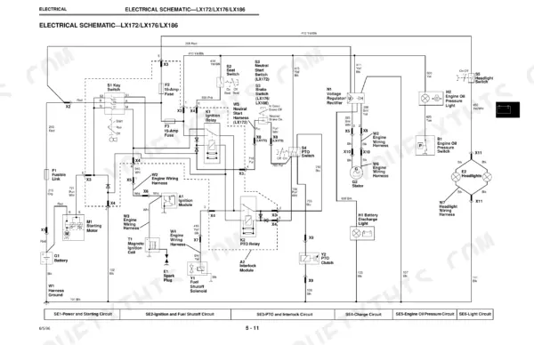
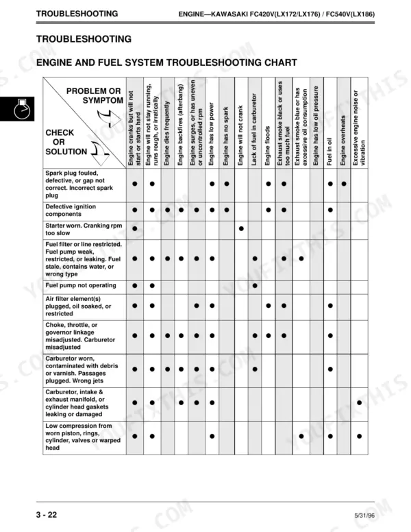
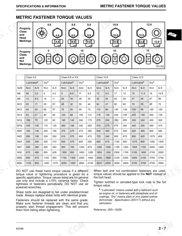
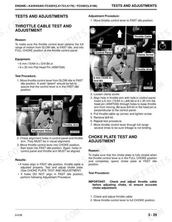
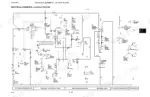
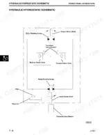
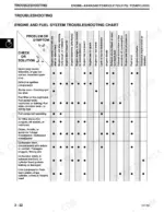
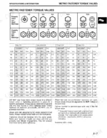
This 660-page John Deere LX172, LX173, LX176, LX178, LX186, LX188 Technical Manual (OEM #TM1492) is the one you want open on your bench for the whole LX family, from air cleaner service to final belt adjustment. You get full wiring diagrams for the electrical system, hydrostatic power train schematics, and a troubleshooting section that walks you through starter faults, fuel pump failures, and steering wander instead of leaving you guessing. Metric and inch fastener torque tables sit right next to the specs section, so you're never cross-referencing a separate sheet. Set your carburetor slow idle at 1450 ±75 rpm and confirm fuel pump flow at a minimum 55 mL per 15 seconds on the FC420V before you close it up. No more chasing an electrical gremlin with a test light and hope. Bookmarked by system and searchable by keyword, so you pull it up on your phone in the shop and jump straight to the page you need.
What's Inside This John Deere LX172 to LX188 Series Manual
| System | Pages | Key Topics |
|---|---|---|
| Introduction | 3 | Safety, Specifications and General Information, Engine, Kawasaki, Kohler, Electrical, Power Train (Gear) |
| Safety | 4-8 | Recognize Safety Information, Handle Fluids Safely-Avoid Fires, Use Care in Handling and Servicing Batteries, Use Safe Service Procedures, Park Machine Safely |
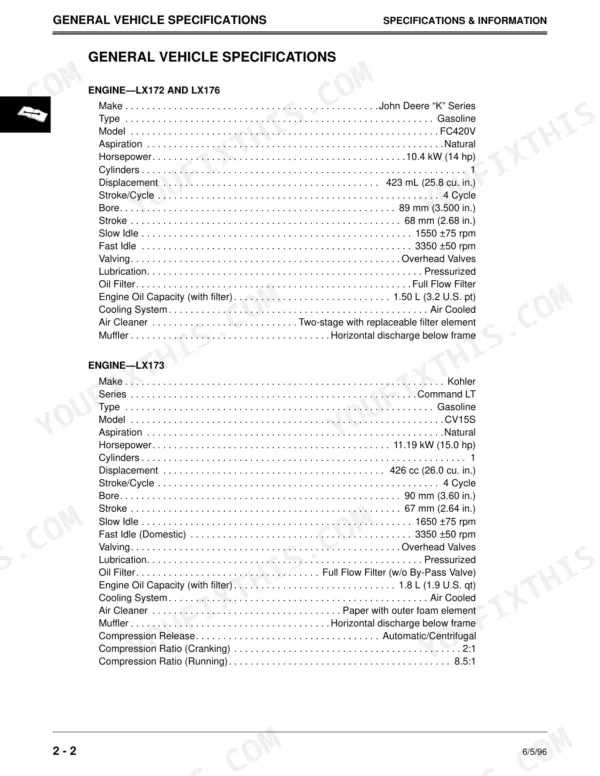
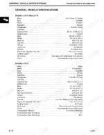
| Specifications & General Information | 9-32 | General Vehicle Specifications, Metric Fastener Torque Values, Inch Fastener Torque Values, Gasoline, Oils and Lubricants, Serial Number Locations |
| Engine Kawasaki | 33-180 | Engine Designation, External Engine Components, Lubrication System Operation, Engine Troubleshooting Guide, Cylinder Compression Pressure Test |
| Engine - Kohler | 181-242 | Engine, Carburetor, Fuel Pump, Oil Filter, Oil Pressure Switch, Valve, Camshaft, Hydraulic Valve Lifters |
| Electrical | 243-460 | Battery, Starter, Stator, Ignition Coil, Spark Plug, PTO Clutch, Coolant Temperature Switch, Electric PTO Clutch |
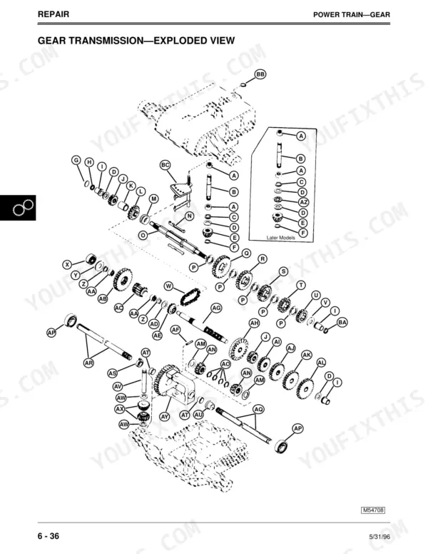
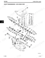
| Power Train - Gear | 461-506 | Transaxle, Shift Lever and Linkage, Traction Drive Clutch Assembly, Clutch Pedal and Linkage, Traction Drive Belt |
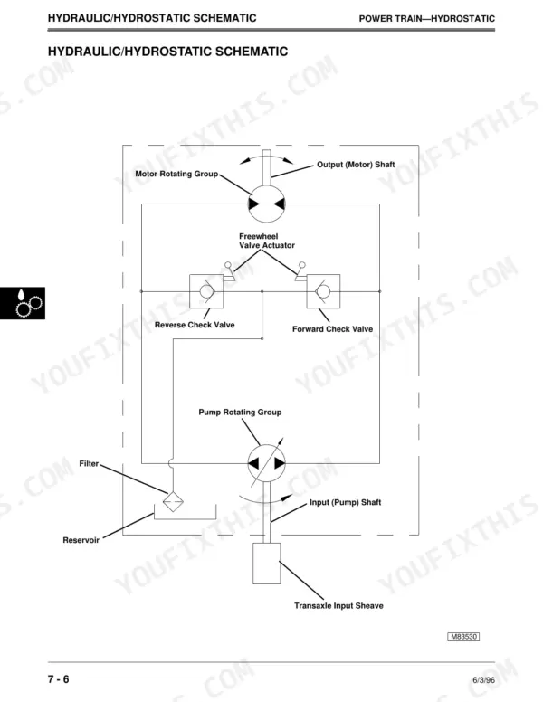
| Power Train - Hydrostatic | 507-568 | Transaxle, Jic Hydraulic Circuit Symbols, Hydraulic/Hydrostatic Schematic, Traction Drive Belt System, Pedal Control System, Hydrostatic System, Transaxle Operation-Gear Power Flow |
| Steering | 569-578 | Steering System Operation, Steering Wander, Lash (Lost Motion) at Steering Wheel, Drag Link Adjustment, Steering Shaft, Steering Sector Assembly |
| Brakes | 579-604 | Brake System Operation, External Brake Linkage Operation, Internal Brake Linkage Operation, Brakes Do Not Engage When Pedal Depressed, Brake Adjustment, Brake Assembly |
| Attachments | 605-644 | Mower Deck, Draft Arms and Gauge Wheels, Idlers and Sheaves, Spindles, Mower Drive Belt, Mower Blades |
| Miscellaneous | 645-652 | Lift Assist and Depth Stop Operation, Front Axle, Spindle Shafts, Wheels, Engine Hood, Mower Deck Lift Linkage |
Quick Reference Specifications
| Specification | Value | Page |
|---|---|---|
| Starter-To-Engine Mounting Cap Screw Torque | 16 N•m (140 lb-in.) | p. 43 |
| Fuel Pump Pressure (Minimum) | 6.12 kPa (0.90 psi) | p. 39 |
| Fuel Pump Flow (Minimum) | 55 mL/15 seconds (1.8 oz/15 seconds) | p. 39 |
| Carburetor SLOW Idle Stop Screw Setting | 1450 ±75 rpm | p. 39 |
| Flywheel Mounting Nut Torque | 88 N•m (65 lb-ft) | p. 112 |
| Starter No Load Amperage Draw/RPM (Maximum) | 50 amps at 6000 rpm | p. 111 |
| Cylinder Head Distortion (Maximum) | 0.06 mm (0.002 in.) | p. 112 |
| Carburetor Mounting Stud Nut Torque | 17 N•m (150 lb-in.) | p. 112 |
| Flywheel Cap Screw Torque | 66.4 N•m (49 lb-ft.) | p. 185 |
| Cylinder Head Cap Screws Initial Torque | 20 N•m (15 lb-ft) | p. 218 |
| PTO Cap Screw Torque | 56 N•m (45 lb-ft) | p. 247 |
John Deere LX172 to LX188 Series Common Problems This Manual Covers
John Deere LX188 tractor suddenly stops running while mowing with no apparent fuel or electrical cause
Check the engine and fuel system troubleshooting chart for overheating and sudden stall symptoms. Remove the cylinder head and inspect the mating surface; maximum allowable distortion is 0.06 mm (0.002 in.). Replace the gasket if pitted or blown, then retorque the flywheel mounting nut to 88 N•m (65 lb-ft) before restarting and load-testing the engine.
Manual Section: Engine and Fuel System Troubleshooting ChartEngine surging or intermittent stalling under load, especially noticeable on hills or heavy grass
Consult the engine and fuel system troubleshooting chart for surging and fuel starvation faults. Test fuel pump output; minimum pressure must read 6.12 kPa (0.90 psi) with steady flow at cranking speed. If pressure is low, clean or replace the pump, then reset the carburetor slow idle stop screw to 1450 ±75 rpm.
Manual Section: Engine and Fuel System Troubleshooting ChartEngine fails to start despite a charged battery and fresh fuel in the tank
Follow the starter motor troubleshooting guide to isolate a no-crank condition. Pull the starter and measure brush length; replace it once worn below the 6 mm (0.240 in.) minimum. Also test the seat and PTO safety interlock switches through the power circuit diagnosis before condemning the starter itself.
Manual Section: Starter Motor Troubleshooting GuideLoss of drive power or transmission slipping when mowing on inclines or under load
Work through the power train gear troubleshooting chart on page 473 to isolate loss of power under load or jerky engagement. Inspect the drive belt for glazing, fraying, or slippage in the pulley grooves, and check idler arm spring tension. Verify pulley and spindle mounting hardware is torqued to 26 N•m (230 lb-in), then road-test in both directions.
Manual Section: Power Train - Gear Troubleshooting Chart p. 473Mower deck or blades will not engage even though the engine cranks and runs
Reference the PTO switch test on page 245 and the electrical system troubleshooting chart to trace the fault. Verify the battery supplies a full 12 V before checking switch continuity with the seat occupied and brake engaged. Replace a failed switch and torque its retaining cap screw to 56 N•m (45 lb-ft) before reassembling.
Manual Section: Electrical System Troubleshooting ChartFrequently Asked Questions
What are the torque specifications for the blade bolt on John Deere LX Series lawn tractors?
The blade cap screw torque varies by mower deck size. For 38-inch mower decks, the torque is 75 N•m (55 lb-ft). For 44-inch rear discharge and 48-inch mower decks, the torque is 68 N•m (50 lb-ft). p. 607
What is the torque specification for the flywheel nut on John Deere LX176?
For the John Deere LX176, which uses the FC420V engine model, the flywheel mounting nut torque is 137 N•m (101 lb-ft). This specification is crucial for proper engine assembly. p. 42
What is the engine oil capacity for the John Deere LX172 and LX176 lawn tractors?
The engine oil capacity for the John Deere LX172 and LX176, when including the filter, is 1.50 L (3.2 U.S. pt). Using the correct oil capacity is important for engine lubrication. p. 10
What is the recommended spark plug gap for the John Deere LX172, LX176, and LX186 lawn tractors?
The recommended spark plug gap for the John Deere LX172, LX176, and LX186 lawn tractors is 0.76 mm (0.030 in.). This ensures proper ignition and engine performance. p. 39
How quickly can I access this John Deere LX172–LX188 Series manual after buying?
You get a 660-page searchable PDF that downloads instantly after checkout. Open it on your laptop, tablet, or phone, and bring it right to the shop floor.
Can I print pages of this John Deere LX172–LX188 Series manual for my own shop?
Yes. Print the pages or sections you need for your own shop use. Any standard printer works.
Does this John Deere LX172–LX188 Series manual include wiring diagrams?
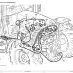
A wiring diagram for the John Deere LX172–LX188 Series electrical system is included.








Reviews
There are no reviews yet.