
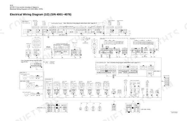
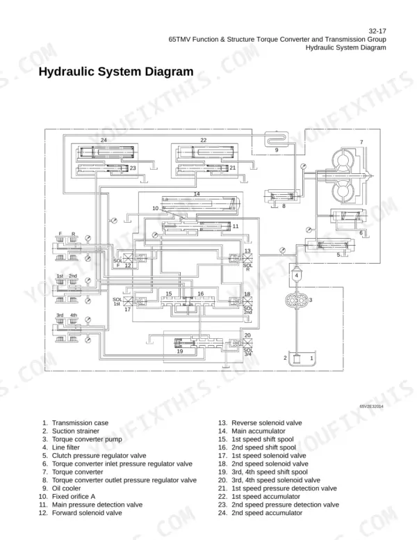
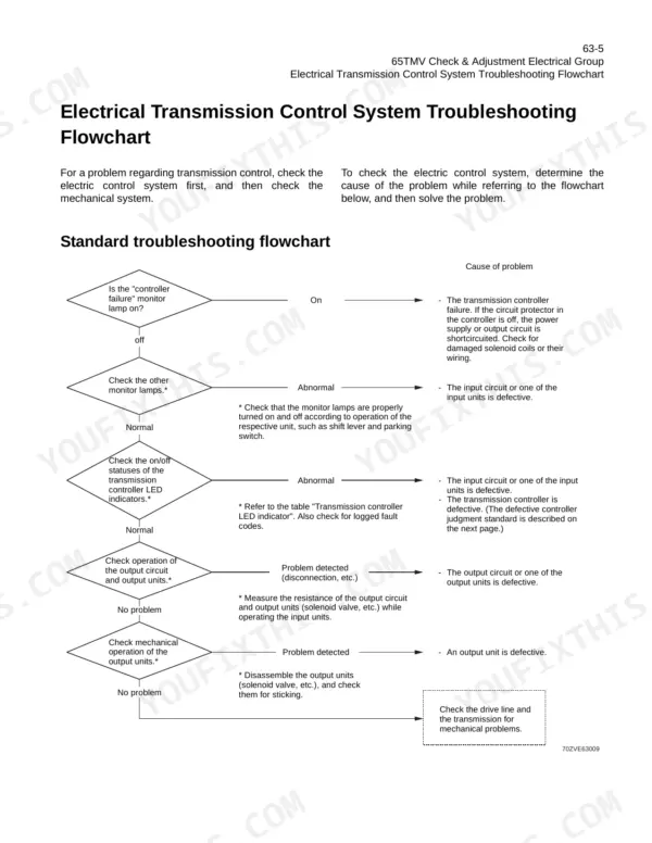
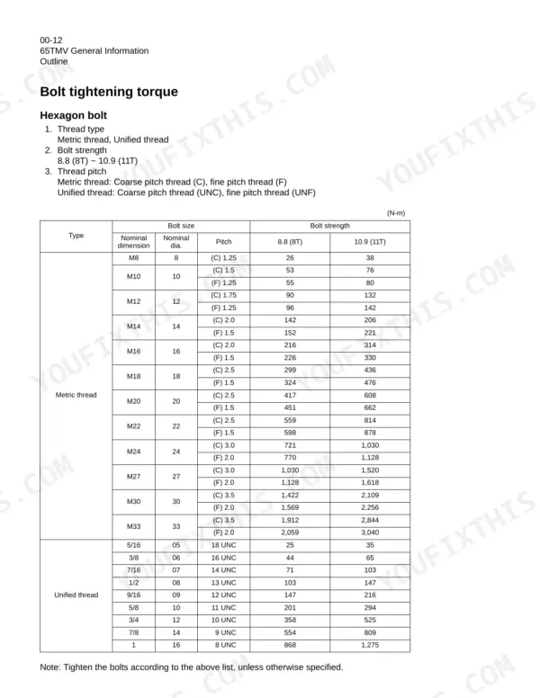
Written for every Kawasaki 65TMV wheel loader from serial number 4001 onward, this Kawasaki 65TMV shop manual PDF (OEM 93207-00233) runs 468 pages and flags the running changes by serial break, so you know which pilot valve and which harness your machine carries. The hydraulic group fills more than a quarter of the book, covering the KML22/2T multiple control valve, Orbitrol steering, ride control, emergency steering and the fan motor line, then the relief valve checks for the loading and steering circuits. Drawings at the back trace the loading/steering hydraulic line, the brake circuit and a wiring diagram for each serial range, while an electrical flowchart walks you through transmission controller faults. Fill the engine with 16 liters (4.2 gal) of oil, and bring M30 grade 8.8 bolts to 1,422 N-m. Trust the wrong serial's diagram and you buy twice. Bookmarks for each group plus a live text layer put you on the right page in seconds.
What's Inside This Kawasaki 65TMV Manual
| System | Pages | Key Topics |
|---|---|---|
| General Information | 1-39 | How to Use Manual, Outline |
| Measurement for Performance Check | 40-43 | Cautions on Safety, Standard Measurement Values for Performance Check |
| Function & Structure Chassis Group | 44-51 | Front Chassis, Rear Chassis, Center Pin |
| Check & Adjustment Chassis Group | 52-55 | Linkage Pin, Center Pin |
| Function & Structure Power Group | 56-75 | Power Line, Engine / Transmission, Radiator, Propeller Shaft, Axle Assembly, Axle Support, Differential Gear |
| Check & Adjustment Power Group | 76-85 | Engine, Propeller Shaft, Axle |
| Function & Structure Torque Converter and Transmission Group | 86-115 | Torque Converter, Torque Converter Gear Pump, Transmission, Clutch Pack, Power Flow Path in the Transmission, Hydraulic System Diagram, Hydraulic Circuit Diagram, Oil Flow |
| Check & Adjustment Torque Converter and Transmission Group | 116-119 | Clutch Oil Pressure |
| Function & Structure Hydraulic Group | 120-237 | Flushing Hydraulic Circuit, Cautions on Hydraulic Parts Replacement, Hydraulic Circuit Symbols, Hydraulic System Operation, Layout of Hydraulic Units, Hydraulic Tank |
| Check & Adjustment Hydraulic Group | 238-255 | Loading/Steering Circuit Relief Valve, Hydraulic Cylinder, Stop Valve, Fan Revolution |
| Function & Structure Brake Group | 256-285 | Brake System Outline, Brake Units Layout, Unloader Valve, Valve Unit, Brake Accumulator Line, Brake Valve, Service Brake, Parking Brake |
| Check & Adjustment Brake Group | 286-295 | Brake Circuit Oil Pressure, Service Brake, Parking Brake |
| Function & Structure Electrical Group | 296-375 | Engine Start Circuit, Power Generating/Charging Circuit, Transmission Control Circuit, Instrument Panel, Diagnostic System |
| Function & Structure Air Conditioner Group | 376-434 | Air Conditioner, Electrical Connections, Maintenance, A/C Charging, Troubleshooting |
| Cross-Section Drawing & Diagrams | 435-468 | Axle Assembly, Torque Converter, Transmission, Hydraulic Line, Brake Circuit, Electrical Equipment Layout |
Quick Reference Specifications
| Specification | Value | Page |
|---|---|---|
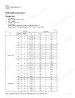
| Hexagon bolt M27 (8.8) torque | 1,030 N-m | p. 29 |
| Hexagon bolt M30 (8.8) torque | 1,422 N-m | p. 29 |
| Breather valve filtration particle size | 10 µm | p. 134 |
| Return filter filtration particle size | 10 µm | p. 134 |
| Engine Oil Capacity | 16 liter (4.2 gal) | p. 25 |
| Transmission Oil Capacity | 20 liter (6.3 gal) | p. 25 |
| Hydraulic Tank Oil Capacity | 75 liter (19.8 gal) | p. 25 |
| Differential & Planetary Oil Capacity (Front) | 25 liter (6.6 gal) | p. 25 |
| Differential & Planetary Oil Capacity (Rear) | 25 liter (6.6 gal) | p. 25 |
| Fuel Tank Capacity | 222 liter (58.6 gal) | p. 25 |
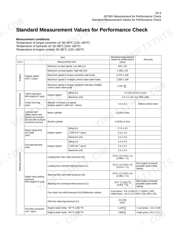
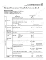
| Main Relief Valve Setting Pressure (Loading) | 20.6 ± 0.5 MPa (2,986 ± 71 psi) | p. 42 |
| Steering Line Main Relief Pressure | 20.6 ± 0.5 MPa (2,986 ± 71 psi) | p. 42 |
Kawasaki 65TMV Common Problems This Manual Covers
Kawasaki 65TMV transmission controller failure with monitor lamp lit and failure code showing on LED indicator
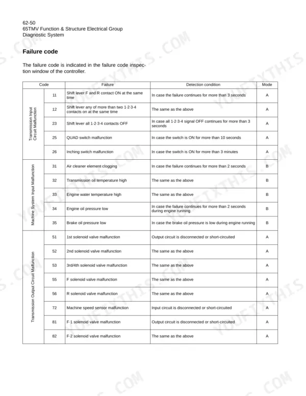
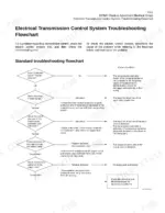
Check the failure code indication through the T/M controller diagnostic system, following the connection procedure and matching the code to the error code reference. Verify LED indicator status and monitor lamp behavior using the procedures, then delete the failure history after the repair and confirm the code stays clear.
Manual Section: Diagnostic System (T/M Controller)Transmission clutch solenoid valve output circuit fault or clutch oil pressure out of spec
Measure clutch solenoid coil resistance and check the diode, then test output circuit voltage per the Clutch Solenoid Valve Output Electrical Circuit Check. If the electrical side passes, measure clutch oil pressure following page 116 to separate an electrical fault from a hydraulic one. Condemn the solenoid only when the coil resistance or diode check fails.
Manual Section: Clutch Solenoid Valve Output Electrical Circuit CheckLoading circuit main relief valve pressure out of spec during hydraulic performance check
Measure loading circuit relief pressure following the performance check procedure on page 42. Verify the main relief valve setting reads 20.6 ± 0.5 MPa (2,986 ± 71 psi). Adjust the loading circuit relief valve per the Check & Adjustment Hydraulic Group on page 238 if the reading falls outside that band.
Manual Section: Check & Adjustment Hydraulic Group p. 238Brake circuit unloader valve cut-in or cut-out pressure and accumulator nitrogen charge out of spec
Check brake circuit oil pressure following page 286 and verify the unloader valve cuts out at 11.8 ± 0.5 MPa (1,706 ± 71 psi) and cuts back in at 6.9 ± 1.0 MPa (995 ± 142 psi). Test accumulator nitrogen gas charging pressure against 2.94 ± 0.1 MPa (427 ± 14 psi) per page 264.
Manual Section: Check & Adjustment Brake Group p. 286Parking brake solenoid electrical circuit fault with abnormal coil resistance or no cable voltage
Measure parking brake solenoid coil resistance, then test cable voltage to the solenoid following the Parking Brake Electrical Circuit Check. Trace the harness against the wiring diagram on page 442 if voltage is missing. Verify parking brake holding performance afterward with the Check & Adjustment Brake Group procedure on page 286.
Manual Section: Parking Brake Electrical Circuit CheckCab air conditioner no cooling, no heat, condenser fans not running or blank display
Check the display first; if it is blank, verify the A/C electrical connections before chasing refrigerant. Test condenser fan operation and actuator door movement following the troubleshooting procedures. Confirm the system charge using the A/C Charging procedure before condemning any components on this cab system.
Manual Section: Air Conditioner TroubleshootingFrequently Asked Questions
How do you reset a Kawasaki 65TMV fault code?
To reset a fault code, turn the starter switch to the ON position (engine OFF) and place the reset switch to the ON position. About 3 seconds later, the auto shift indicator lamp [AUTO] and all warning lamps will light up and the indication of "FF" on the diagnosis display window will disappear. After the inspection window goes blank, place the reset switch to the OFF position. The buzzer will sound, indicating the failure history deletion is complete. p. 348
Where can I find the error codes for the Kawasaki 65TMV?
The failure codes for the Kawasaki 65TMV are listed in the 'Diagnostic System' section on pages 345 and 346. These codes are indicated in the failure code inspection window of the controller. p. 345
What is the engine oil and oil filter cartridge replacement interval on the Kawasaki 65TMV?
The engine oil and oil filter cartridge should be replaced every 250 operating hours. p. 22
What is the axle shaft bolt tightening torque on the Kawasaki 65TMV wheel loader?
The axle shaft bolt (1) must be tightened to 314 N-m (32.0 kgf-m) (232 lb-ft). p. 80
Is this Kawasaki 65TMV manual a PDF I download?
One searchable PDF covering 468 pages, delivered instantly. No disc, no shipping, no waiting on the post.
Can I print just the pages I need from this Kawasaki 65TMV manual?
You can. The PDF is unlocked and carries no copy protection, so print the sections you want and keep the file as your backup.
Does this Kawasaki 65TMV manual show the hydraulic circuits?
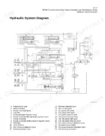
The Kawasaki 65TMV Shop Manual includes full hydraulic circuit diagrams, valve body layouts, and component specs. There is one on page 102, for example.


Reviews
There are no reviews yet.