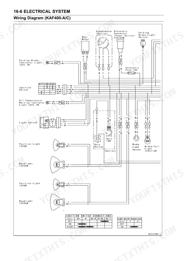
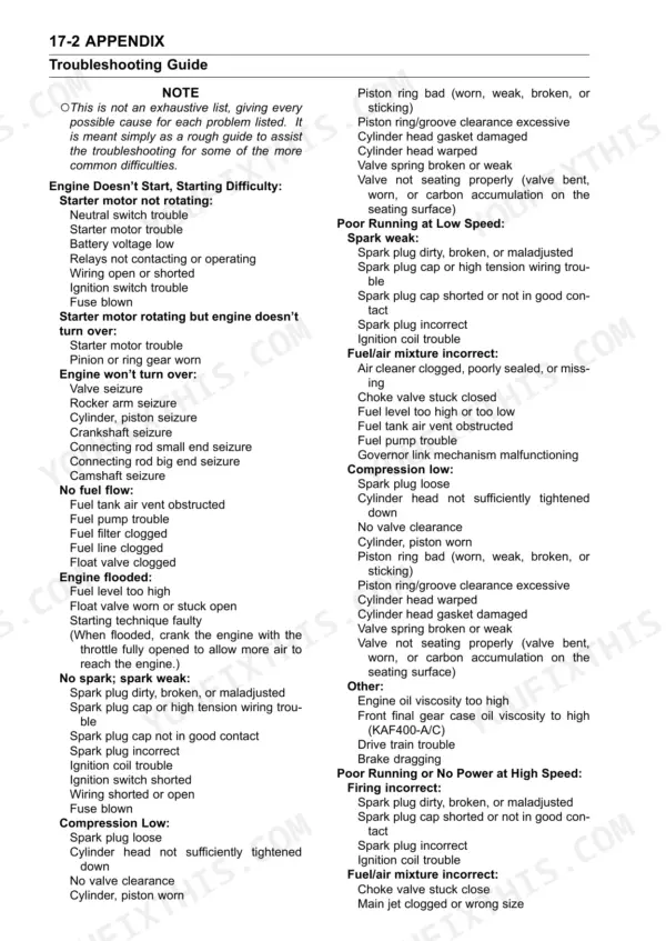
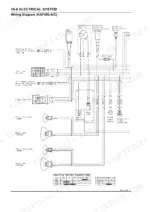
Pulling the CVT cover on a Mule this afternoon goes easier with this 409-page Kawasaki Mule 600 service manual PDF (OEM 99924-1349-01) open beside you. It is written for the KAF400 utility vehicle series and covers seven model designations, the Mule 610 4x4 included. Wiring diagrams for the ignition and charging circuits anchor the electrical chapter, one of the longest in the book, and the appendix finishes with a troubleshooting guide plus cable, wire, and hose routing. Converter work has its own chapter, running from the drive and driven pulleys through the torque converter. Measure your drive belt width first: standard is 26.1 to 27.3 mm, and anything under 25.2 mm comes out; gap the plug at 0.7 to 0.8 mm. Out at the back fence, it's you, the Mule, and nobody to ask. Bookmarked chapters and a live text layer take you to the one section you need in a couple of clicks.
What's Inside This Manual
| System | Pages | Key Topics |
|---|
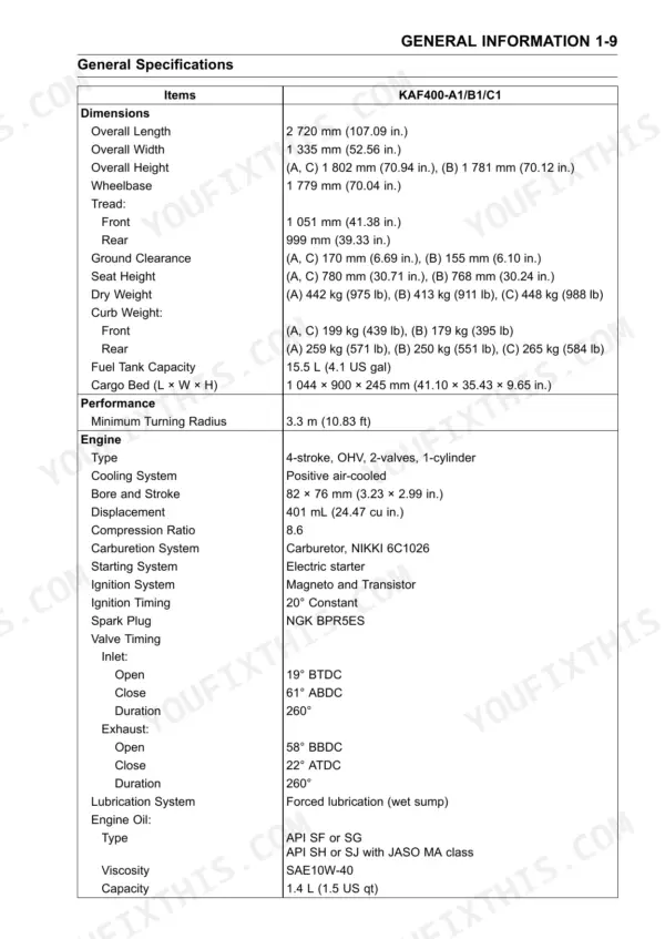
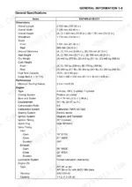
| General Information | 9-20 | Before Servicing, Model Identification, General Specifications |
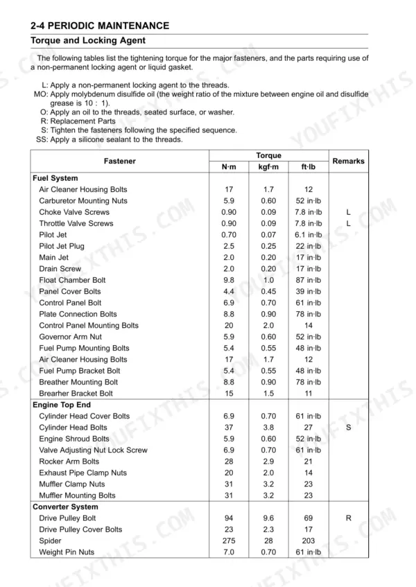
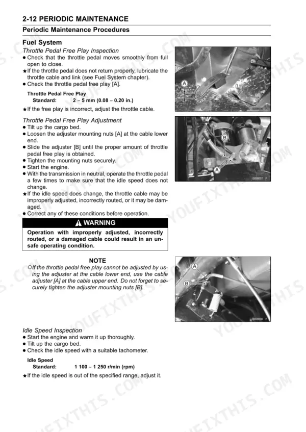
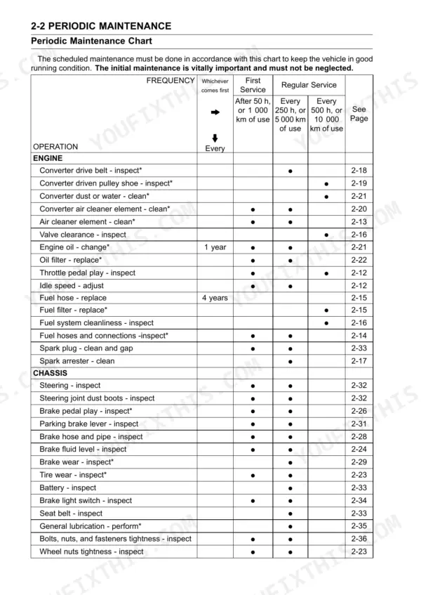
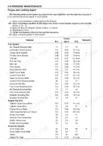
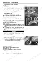
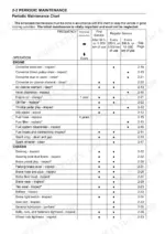
| Periodic Maintenance | 21-58 | Periodic Maintenance Chart, Torque and Locking Agent, Periodic Maintenance Procedures |
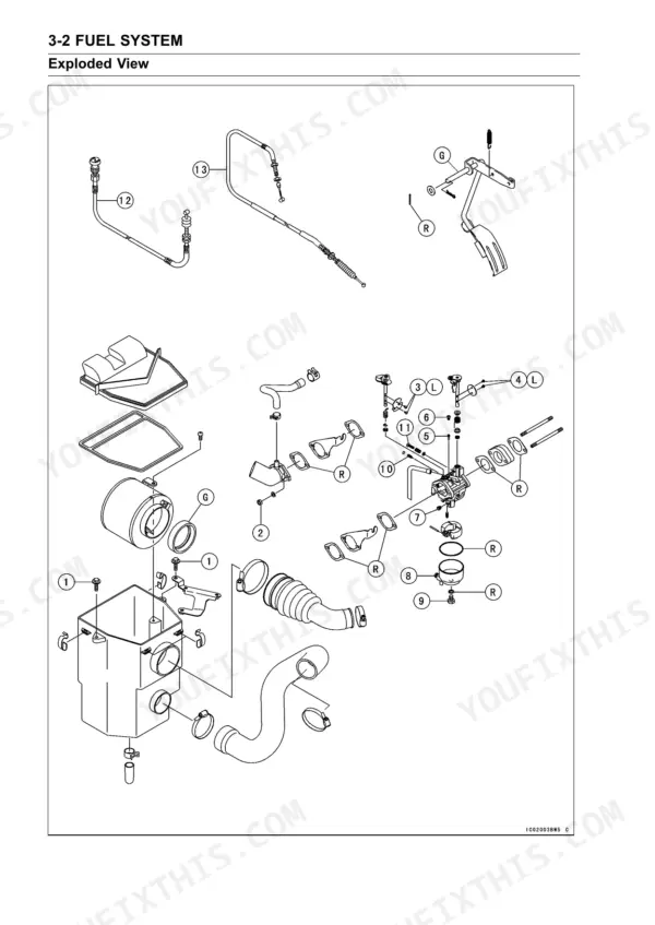
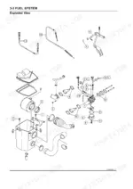
| Fuel System | 59-84 | Throttle Pedal and Cable, Governor Link Mechanism, Carburetor |
| Engine Top End | 85-102 | Cylinder Head, Valves, Exhaust Pipe and Muffler |
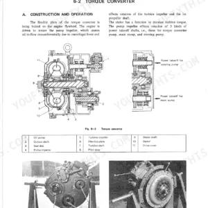
| Converter System | 103-130 | Torque Converter, Drive Pulley, Driven Pulley |
| Engine Lubrication System | 131-142 | Oil Pump and Relief Valve, Oil Screen |
| Engine Removal/Installation | 143-150 | Engine Removal, Engine Installation |
| Engine Bottom End | 151-174 | Camshaft and Tappets, Cylinders and Pistons, Crankshaft and Connecting Rods |
| Transmission | 175-212 | Transmission Case, Transmission and Shift Mechanism, Differential Gears and Shift Mechanism |
| Wheels/Tires | 213-222 | Wheel Alignment, Wheels, Tires |
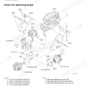
| Final Drive | 223-268 | Front Final Gear Case, Bevel Gear Case, Propeller Shafts |
| Brakes | 269-290 | Brake Fluid, Brake Pedal and Master Cylinder, Brake Panel Assemblies |
| Suspension | 291-302 | Struts and Rear Shock Absorbers, Front Suspension Arms, Swingarm |
| Steering | 303-314 | Steering Wheel and Main Shaft Assembly, Steering Gear Assembly, Steering Knuckles |
| Frame | 315-336 | Seat and Seat Belts, Control Panel, Cargo Bed |
| Electrical System | 337-388 | Battery, Charging System, Ignition System |
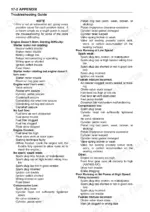
| Appendix | 389-409 | Troubleshooting Guide, Cable, Wire, And Hose Routing |
Quick Reference Specifications
| Specification | Value | Page |
|---|
| Engine Oil Drain Plugs Torque | 6.9 N·m (0.70 kgf·m, 61 in·lb) | p. 133 |
| Ring Gear Cover Bolts M10 Torque | 47 N·m (4.8 kgf·m, 35 ft·lb) | p. 233 |
| Drive Belt Width Standard | 26.1 - 27.3 mm | p. 29 |
| Drive Belt Width Service Limit | 25.2 mm | p. 29 |
| Spark Plug Gap | 0.7 - 0.8 mm | p. 30 |
| Oil Filter Joint Torque | 6.9 N·m (0.70 kgf·m, 61 in·lb) | p. 133 |
| Battery Capacity | 12 V 14 Ah | p. 19 |
| Carburetor Mounting Nuts Torque | 6.9 N·m (0.70 kgf·m, 61 in·lb) | p. 61 |
| Choke Valve Screws Torque | 0.90 N·m (0.09 kgf·m, 7.8 in·lb) | p. 61 |
| Air Cleaner Housing Bolts Torque | 17 N·m (1.7 kgf·m, 12 ft·lb) | p. 80 |
| Fuel Pump Bracket Bolt Torque | 5.4 N·m (0.55 kgf·m, 48 in·lb) | p. 80 |
| Ring Gear Cover Bolts M8 Torque | 25 N·m (2.6 kgf·m, 19 ft·lb) | p. 233 |